| Diesel, Engine Technology and Vehicle Technology. Repair, Maintenance and Diagnostics (OBD). |
Vacuum system and control pneumatics in the TDI (Articles) |
|
|
| 🔗 ⭐ 🖨 |
| Vacuum system and control pneumatics in the TDI | ||||||||||||||||||||||||||||||||||||||||||||||||||||||||||||||||||||||||||||||||||||||||||||||||||||
|---|---|---|---|---|---|---|---|---|---|---|---|---|---|---|---|---|---|---|---|---|---|---|---|---|---|---|---|---|---|---|---|---|---|---|---|---|---|---|---|---|---|---|---|---|---|---|---|---|---|---|---|---|---|---|---|---|---|---|---|---|---|---|---|---|---|---|---|---|---|---|---|---|---|---|---|---|---|---|---|---|---|---|---|---|---|---|---|---|---|---|---|---|---|---|---|---|---|---|---|---|
ulf  12-06-2003, 18:25 12-06-2003, 18:25 |
||||||||||||||||||||||||||||||||||||||||||||||||||||||||||||||||||||||||||||||||||||||||||||||||||||
In TDI engines, the turbocharger control, the AGR, and the intake manifold flap, used to reduce vibrations when the engine is stopped, are typically pneumatically actuated. In newer pump-injector and common-rail TDIs, the idle control valve/throttle valve and the AGR valve are usually electrically actuated. These swirl flaps (which, in engines with four valves, close off an intake channel for exhaust-related reasons) are usually also actuated pneumatically.
The tangle of thin tubes in the engine compartment can be daunting when troubleshooting, although the functionality of the individual systems is always the same for each engine generation.
Detailed hose diagrams for each engine would exceed the scope of this presentation. Therefore, the following images show the general structure of the common hose systems, which is the same for all engines. Depending on the engine, not all systems are present (e.g., the shut-off valve), or other combinations can be found (e.g., a wastegate engine with EGR). Nevertheless, when troubleshooting, you can refer to the relevant diagram and error table that describes the specific system in question.
The depiction of the simple hose from the intake manifold to the boost pressure sensor (as a separate part or within the MSG) has been omitted in older engine models.
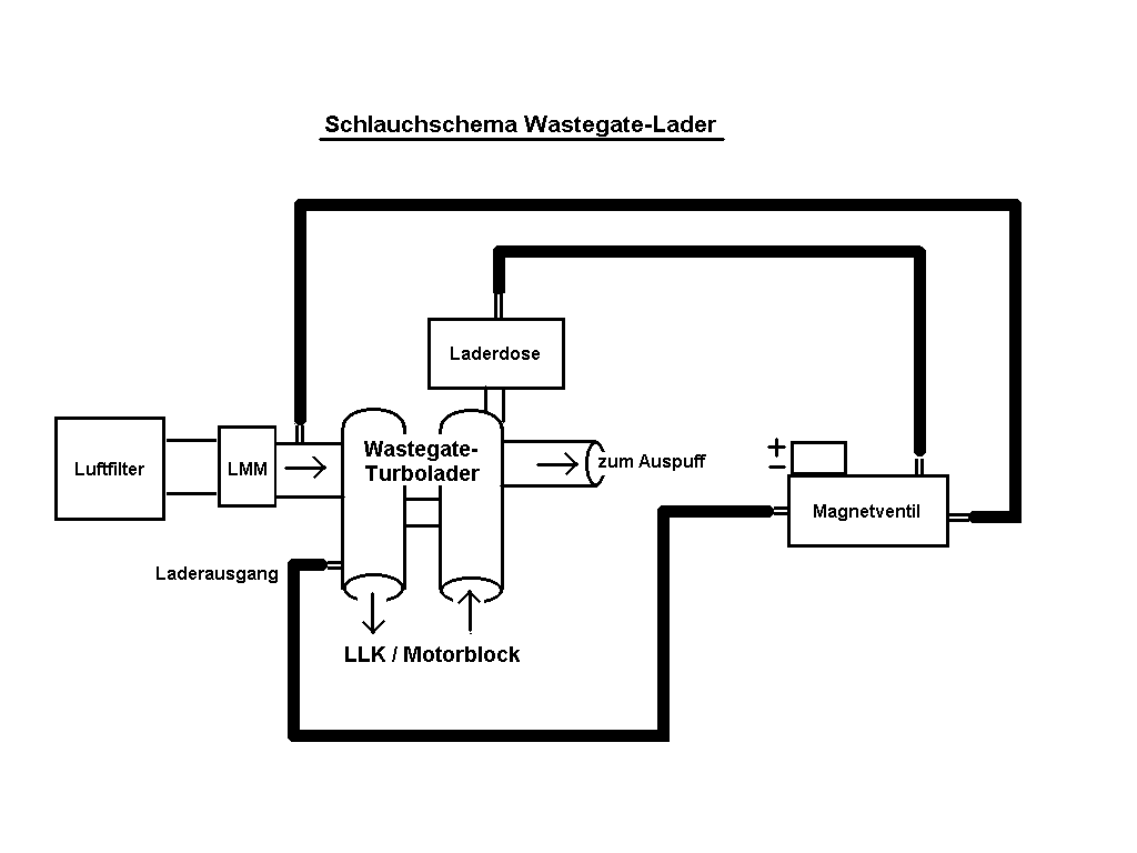
The regulated wastegate turbocharger (e.g., in the 1Z, AHU, AAT, AEL engines) has a conventional diaphragm system with a spring that opens the wastegate at approximately 0.6 bar of boost pressure, preventing a further increase in boost pressure.
The monitoring of the boost pressure using an electronic pressure sensor and the control of the solenoid valve for boost pressure correction are performed by the engine control unit (ECU). Active control at a boost pressure below 0.6 bar is not possible.
In case of incorrect charging pressure, the charger inlet can be directly connected to the charger membrane sensor for problem identification.
.
The type of turbocharger can be identified by the hose routing: If one of the hoses from the boost pressure solenoid valve leads towards the turbocharger outlet (or the intake manifold between the turbocharger and the engine), then it is a wastegate turbocharger. Führt ein Schlauch stattdessen (über T-Stücke usw.) zur Unterdruckpumpe, so ist ein VTG-Lader verbaut.
The VTG turbocharger system , which uses a membrane dose controlled by vacuum, is not stable and cannot operate reliably without constant electronic control, unlike a wastegate turbocharger.
Der Ladedruck wird vom MSG ständig überwacht, mit dem Sollwert laut Kennfeld verglichen und durch Ansteuern eines Magnetventils korrigiert.
Without vacuum at the diaphragm, no boost pressure is generated.
a check valve and a vacuum reservoir, which is located on a hose branch behind the check valve, as viewed from the pump.
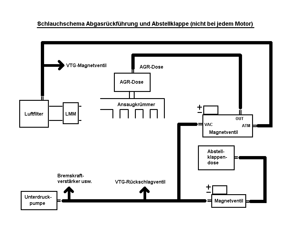
Die unterdruckbetätigte AGR-Membrandose am Ansaugkrümmer bewegt das AGR-Ventil. Without vacuum, the valve is closed.
The constant monitoring and correction of the AGR rate, achieved by controlling the solenoid valve, is performed by the MSG (Motor Steuergerät) based on the mass airflow sensor (MAF) signal.
In some engines, the EGR pneumatic system is also supplied from the vacuum reservoir instead of directly from the pump.
Since the throttle valve only needs to be fully open or fully closed, its diaphragm requires no continuous pressure control. When parking, a simple solenoid valve is activated, which connects the vacuum supply to the diaphragm chamber.
Most engines have separate solenoid valves for VTG and EGR. Da beide Ventile an ihren Eingängen jeweils Unter- und Außendruck benötigen, verzweigen sich die Schlauchführungen von der Unterdruckpumpe bzw. dem Außendruckabgriff über T-Stücke zu den Ventilen.
In the VTG vacuum system, in addition to the above-mentioned, there is also... Check valve and vacuum reservoir.
The branch for the shut-off valve is supplied from the hoses to the vacuum pump.
The latter hoses are never branched; if they are, it indicates a mounting error that can lead to all sorts of malfunctions.
Although the basic principle of VTG and AGR control is the same, many engines use different solenoid valves, which can be identified by the part number and sometimes also by the color.
The valves differ, among other things, in their internal flow cross-sections. If the valves are swapped, the systems will remain fundamentally functional, but the response and control characteristics will be altered.
Some (mainly newer) engines have several solenoid valves grouped together in a block, but the functionality of each individual system is always as described above. In some cases, only one external and one internal pressure line connect to the valve block, with the necessary branch connections integrated within the block itself.
The functions of the individual valves can be determined by examining the hoses connected to their outlets: the line from the charge air pressure sensor leads directly to the charge pressure solenoid valve, etc.
In the case of sensors that are located separately, a hose always leads from the sensor to the intake manifold. Intake manifold.
To do this, use VCDS to access the engine control unit and select the basic settings in measuring block 3 or 11. For newer engines, you can use the selective actuator diagnosis for testing. The actuators are alternately driven to their minimum and maximum positions.
, a complete blockage of the relevant component is assumed. A piece of the hose came loose.
https://community.dieselschrauber.org/en/viewtopic.php?t=15788 Translated on 03-07-2026, 15:19. |
||||||||||||||||||||||||||||||||||||||||||||||||||||||||||||||||||||||||||||||||||||||||||||||||||||
 |
||||||||||||||||||||||||||||||||||||||||||||||||||||||||||||||||||||||||||||||||||||||||||||||||||||
| Ratings - Vacuum system and control pneumatics in the TDI | |
Average rating: 5.00 - worst rating: 5 - best rating: 5 - number of ratings: 18 - View ratings |
|
|
| 🔗 ⭐ 🖨 |
|
|||||||||||||
|
You cannot post new topics in this forum. |
|||||||||||||
|
Foren- und Portal-Software: V7.9 © 2003 - 2026 Kaufmann Automotive GmbH, Embedded Software Freelancer & Shop für Kfz-Diagnosegeräte. Parse time: 0.080s
 |


 Bookmarks
 Links
Links Garage
 FAQ, Legal Notice & Privacy
 RSS Feed
 Register
 Login
Login