| Author |
Message |
kubs
Guest
Free account, no CAN development support
|
 11-12-2004, 10:46 Subject: Pinout for control unit 1Z? 11-12-2004, 10:46 Subject: Pinout for control unit 1Z? |
Quote |
|
Hi,
I need the pinout diagram for a 1Z control unit from a 1994 Passat TDI. VAG-COM says the following:
Engine control unit: 028 906 021 B
Component: 1.9L R4 EDC SG D44
Encoding: 00000
Workshop code: WSC 00000
I want to find out what the previous owner modified on the steering device of my Passat. So far, it has exhibited the following phenomenon:
- The idle speed control is not functioning correctly and cannot be adjusted using VAG-Com. When you release the accelerator, the engine doesn't automatically return to its idle speed, but instead stays at approximately 1100 RPM.
And sometimes, the car will go around the curves in 30 km/h zones with a surprisingly high 'idle' speed, 'without' the driver needing to press the accelerator! :fire_balloon:
You only achieve the actual engine speed by keeping one foot on the brake and giving it a quick burst of gas with the other foot twice. ?
At first, I thought it might be the potentiometer, so I replaced it. However, that didn't make any difference. The error log repeatedly shows '777: Implausible gas signal.'
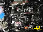
I found some pre-soldered diodes on the connector to the control unit, and they don't look very original VAG. Unfortunately, I can't understand what they are for.
While I was inspecting something, the resistors unfortunately broke. Since I didn't have anything suitable to replace them with, I used a cable instead, and lo and behold, everything is working perfectly now. The idle speed regulation is working flawlessly. But is it really that good?
Does anyone have a pinout for me, or can someone help me identify '' based on the image?
Regards,
Stefanhttp://www.35i-forum.de/forum/thread.php?threadid=24465&sid=
|
|
| Back to top |
|
 |
guste100
Profi-Schrauber


Joined: 07/27/2004
Posts: 2399
Karma: +435 / -0 
Location: Mitte Schleswig Holsteins
2007 Volkswagen Passat
Premium Support
|
| 11-12-2004, 11:57 Subject: Pinout for control unit 1Z? |
Quote |
|
Look here!
Regards,
Guste. |
|
| Back to top |
Profile PM Garage |
|
Rudi
Guest
Free account, no CAN development support
|
| 12-12-2004, 23:28 Subject: Pinout for control unit 1Z? |
Quote |
|
Hi,
Thank you for the flowers, Guste  .
However, there are slight variations in the older MSA12 models (021B, 021C).
I don't remember which ones.
@Stefan:
If you are not satisfied with the results due to the pin configuration...
You can come here to post, or send me a private message.
Best regards, Rudi. |
|
| Back to top |
|
|
kubs
Guest
Free account, no CAN development support
|
| 13-12-2004, 10:44 Subject: Pinout for control unit 1Z? |
Quote |
|
I have no idea where pin 1, etc., starts, but after replacing the resistors with a cable, everything is working fine.
No more entries in the error memory, soot formation has decreased, driving performance is okay, and finally, I'm also seeing 0% throttle in VAG-com at idle, instead of the usual 3.5%.
It seems like my previous owner messed something up.
I, for one, don't understand why someone would install something like a '10-cent tuning' modification on a Passat that already has an ECU chip from ***. And I think it's ridiculous that BOSCH/VW is giving me a new...
He wants to sell turbochargers, throttle position sensors, etc., and hasn't even found the problem!
Regards  |
|
| Back to top |
|
|
Rudi
Guest
Free account, no CAN development support
|
| 13-12-2004, 11:39 Subject: Pinout for control unit 1Z? |
Quote |
|
Hi,
It would still be interesting to know what he messed up.
Pin layout attached.
Best regards,
| Description: |
| Pinout for control unit 1Z? |
|
| File size: |
51.84 KB |
| Viewed: |
27488 times |

|
|
|
| Back to top |
|
|
dieselschrauber
Administrator

Joined: 04/12/2002
Posts: 17996
Karma: +782 / -0
Location: St.Gallen
2018 Volkswagen T6 
|
| 31-05-2024, 14:41 Subject: Pinout for control unit 1Z? |
Quote |
|
Quote: | MSA12/15 (68 poles)
PIN DESCRIPTION.
Please provide the German text you would like me to translate into English.
1 Battery Negative.
2. Speed signal.
3 blower relays.
4 turnout frames.
5 turnout frames.
6 Glow plug heater elements, type 1. Group.
7 Rule-based systems, mid-level abstraction.
8 speed sensor signals.
9. Speed-quantity signal.
10 nc
11 Needle movement sensors, sensor ground.
12 Needle movement sensor signal.
13 LMM signal.
14 Water temperature sensor signals.
15 Pedal position sensor signals.
16?
17 Clutch switch signal.
18 Automatic transmission feedback signal.
19 LMM +5V
20 Redundant brake contact.
21 nc
22 nc
23 Battery Plus.
24 Battery Negative.
25 Exhaust gas recirculation (EGR) valves.
26 Glow plug heater, version 2. Group.
27 nc
28 Climate Performance Output.
29 Standardized Current-Controlled Reference Coil.
30 Summary message: Glow monitoring.
31 Pulse width modulation output signal.
32 Kickdown signal, output.
33 Analog measurement ranges.
34 GRA 'Resumption'
35 GRA 'Acceleration'
36 nc
37 Climate change alarm signal.
38 KL15, digital information for EDC.
39. Generator load input signal.
40 nc
41 nc
42 Main Relay Control.
43. Vehicle speed sensor signal.
44 Brake light switch signal.
45 Battery Plus.
46 Battery Negative.
47 boost pressure regulators.
48 System Light.
49-way turnout.
50 relay modules.
51 Magnetic valve injection adjuster.
52 Standardized measuring coils.
53 Electrical. Parking (positive sign).
54 nc
55 throttle position sensors, sensor mass.
56 nc
57 Pedal position sensors +5V
58 Input channels for glow plug ignition.
59 nc
60 nc
61 K-leaders, according to the ranking. ISO protocol.
62 Kickdown signal input.
63. Fuel temperature sensor signal.
64 Intake air temperature sensor signals.
65 Idle speed control signal.
66 GRA 'Delete'
67 nc
68 Battery Plus | Dipl.-Ing. (FH) Rainer Kaufmann - dieselschrauber VCDS Shop |
|
| Back to top |
Profile PM WWW Garage |
|
|

