| Diesel technology, engine technology, vehicle diagnostics, repair & maintenance. |
{SYSTEM NAME} Pressure Control System and Pneumatics on TDI (Articles) |
|
|
| 🔗 ⭐ 🖨 |
| {SYSTEM NAME} Pressure Control System and Pneumatics on TDI | ||||||||||||||||||||||||||||||||||||||||||||||||||||||||||||||||||||||||||||||||||||||||||||||||||||
|---|---|---|---|---|---|---|---|---|---|---|---|---|---|---|---|---|---|---|---|---|---|---|---|---|---|---|---|---|---|---|---|---|---|---|---|---|---|---|---|---|---|---|---|---|---|---|---|---|---|---|---|---|---|---|---|---|---|---|---|---|---|---|---|---|---|---|---|---|---|---|---|---|---|---|---|---|---|---|---|---|---|---|---|---|---|---|---|---|---|---|---|---|---|---|---|---|---|---|---|---|
| ulf |
||||||||||||||||||||||||||||||||||||||||||||||||||||||||||||||||||||||||||||||||||||||||||||||||||||
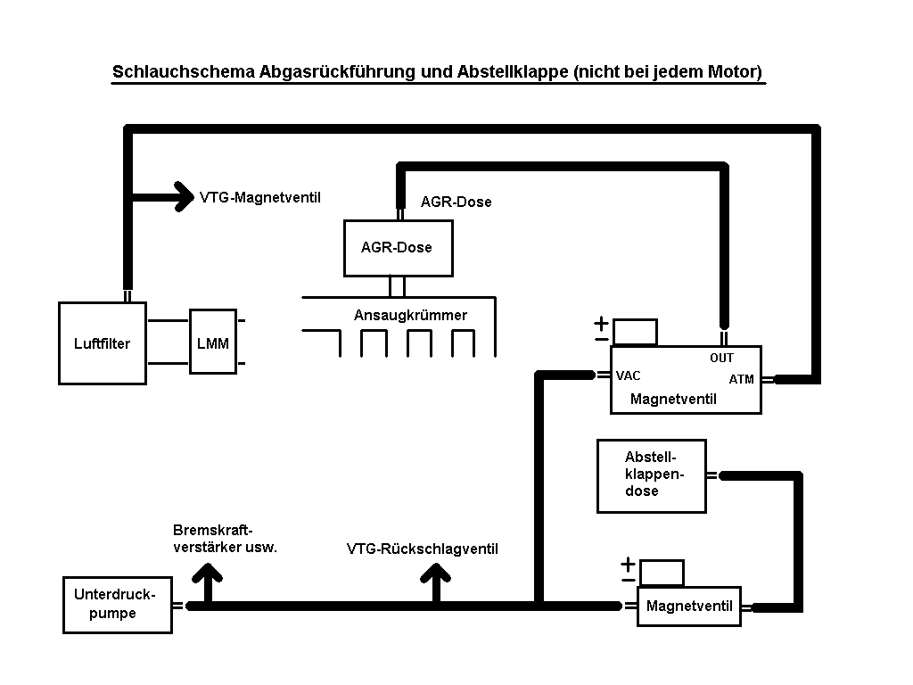
In TDI engines, the turbocharger control, the AGR and the intake valve are primarily pneumatically operated to reduce vibrations when the engine is stopped. In newer pump-nozzle and common-rail TDIs, the shut-off valve/throttle valve and the AGR valve are typically electrically operated. These are the control valves (which, in most 4-valve engines, close an intake channel for exhaust reasons) and are typically pneumatically operated.
The tangled mess of thin hoses in the engine compartment can be intimidating when troubleshooting, even though the functionality of individual systems is always the same for each engine generation.
Detailed hose diagrams for each engine would exceed the scope of the illustration. Therefore, the following images show the basic structure of common hose systems, which is the same for all engines.
Depending on the engine, not all systems are present (e.g., the parking flap) or other combinations (e.g., a Wastegate engine with AGR) can be found. Nevertheless, one can refer to the diagram and the error table, in which the relevant system is described, when troubleshooting.
Instead, the simple hose from the intake to the boost pressure sensor (as a separate part or integrated in the MAP sensor) used in older engines has been omitted.
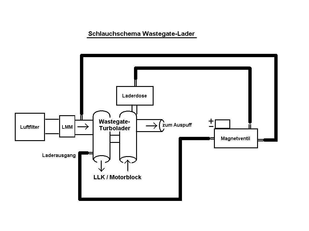
The regulated wastegate diverter (e.g., in 1Z, AHU, AAT, AEL) has a conventional diaphragm-type unit with a spring, which opens the wastegate at approximately 0.6 bar of boost pressure and prevents further increase in boost pressure.
The charging pressure is monitored using an electronic pressure sensor, and the charging pressure correction is controlled by the engine control unit (ECU). An active regulation at a boost pressure of less than 0.6 bar is not possible.
If the boost pressure is incorrect, the boost inlet can be directly connected to the boost solenoid housing for troubleshooting purposes.
Identifying the type of charger is possible by examining the hose routing: If one of the hoses leads from the charger's solenoid valve towards the loading outlet (or the intake pipe between the charger and the engine), it is a wastegate charger. Instead, a hose leads to the vacuum pump (via T-pieces, etc.), in which case a VTG charger is installed.
The The boost pressure is constantly monitored by the MSG, compared to the target value according to the characteristic curve, and corrected by actuating a solenoid valve.
This mixes the pressure coming from the vacuum pump with the external pressure (the outlet is usually in the range of the air filter), which allows for continuous adjustment of the VTG mechanism: The stronger the vacuum at the membrane housing, the more boost pressure is built up or the initial pressure build-up is shifted to lower engine speeds. To achieve precise charging pressure control, the vacuum at the inlet of the solenoid valve must be as constant as possible. Since vacuum pumps generate pulsations, the vacuum is regulated using a check valve and a vacuum storage , which is located behind the check valve on a pipe branch, as seen from the pump.
The vacuum-operated AGR membrane housing on the intake manifold moves the AGR valve. Without vacuum, the valve is closed.
The underpressure for the stepless operation of the AGR is mixed from under- and overpressure, similar to the VTG loader. In some engines, the EGR pneumatic system is also supplied from the vacuum reservoir instead of directly from the pump.
TDIs of the AHF, ALH, ASV, etc. generations have a vacuum-operated suction valve that closes when the engine is stopped. The resulting reduction in compression reduces vibrations during engine startup. Pneumatic control system hose routing for various engines In the VTG undercarriage system, in addition to the aforementioned, there is also... Backflow preventer and the vacuum accumulator.
The branch for the stowage flap is supplied with air from the vacuum pump hoses.
The connections of the solenoid valves are usually marked: for example, ATM must be connected to the external pressure pickup, VAC to the vacuum pump or vacuum reservoir, and OUT to the membrane chamber of the part to be controlled. Although the basic principle of VTG and AGR control is the same, many engines use different solenoid valves, which can be identified by the part number and sometimes also by color.
The valves differ from each other, among other things, in their internal flow cross-sections. If you swap the valves, the systems will still function in principle, but the responsiveness and control behavior will be changed.
Some (primarily newer) engines have multiple solenoid valves combined into a single block, but the operation of each individual system is always as described above. Sometimes, only one external and one internal line lead into the valve block. The necessary branches are then integrated into the block.
The functions of each valve can be determined by examining the connections at their outlets: the line from the compressor diaphragm valve leads directly to the boost solenoid valve, etc.
In some engines, the boost pressure sensor is located in the intake manifold (with at least 3 electrical connections), while in others it is mounted separately in the MSG, or it is designed as a separate component. AGR and VTG/Wastegate can be tested for functionality using the VCDS automotive diagnostic software from the Dieselschrauber Shop. To do this, you use VCDS to access the engine control unit and select the basic settings in block 3 or 11, and for newer engines, you can use the selective actuator diagnostic function to test. Typical failure symptoms in the area of the throttle valve (only applicable to older TDIs for the AGR) The statements regarding the charging pressure refer to full load over approximately 2000 minutes-1.
Last edited on 13-02-2017, 13:44, edited 2 times in total. |
||||||||||||||||||||||||||||||||||||||||||||||||||||||||||||||||||||||||||||||||||||||||||||||||||||
| Ratings - {SYSTEM NAME} Pressure Control System and Pneumatics on TDI | |
Average rating: 5.00 - worst rating: 5 - best rating: 5 - number of ratings: 18 - View ratings |
|
|
| 🔗 ⭐ 🖨 |
|
|||||||||||||
|
You cannot post new topics in this forum. |
|||||||||||||
|
Foren- und Portal-Software: V7.1 © 2003 - 2026 Kaufmann Automotive GmbH, Embedded Softwareentwicklung & Shop für VCDS und OBD-Diagnosegeräte. Parse time: 0.070s
|
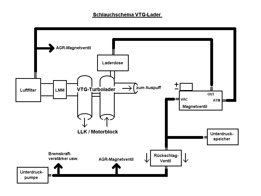 VTG-charger system, which uses a membrane box operating under vacuum, is, unlike a wastegate-charger system, not permanently stable and operable without constant electronic control.