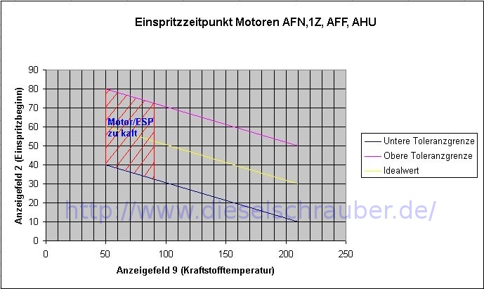
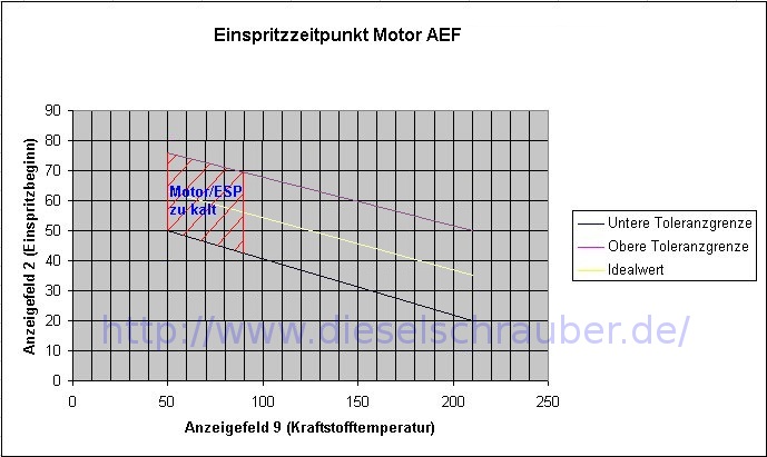
I would like to thank Ulf for the part of the setup that uses DIY methods.
Adjustment using DIY methods:Before explaining the method, here is a brief description of how the injection adjustment works.
The VP 37 injection pump, like the older, purely mechanical Bosch distributor pumps, has a hydraulic injection advance control, which causes an advance that increases with the engine speed. This is (mainly to adjust to the instantaneous injection quantity) reduced by the engine computer to the point where the injection start reported by the needle position sensor matches the target value according to the characteristic map. To achieve this, it controls an electric valve (injection adjuster) that diverts a portion of the fuel from the hydraulic injection advance control.
Without tax voltage, the injection control valve remains closed, and thus the hydraulic advance is fully effective, which is approximately equivalent to full load operation. As the tax voltage increases, the injection control valve opens further, thereby reducing the advance more and more. This occurs at partial load or idle.
To control the fuel injector adjuster, the engine computer rapidly switches the full on-board voltage on and off in a sequence with variable time durations ("duty cycle"), resulting in effective voltages ranging from just above zero to approximately 13 volts.
With a target resistance of 12-20 ohms, the maximum current for the spark arrester is in the range of 1 ampere.
The active adjustment range of the pump (starting from the default setting) is only slightly larger than the difference between the earliest and latest desired injection start times, as specified in the characteristic curve.
This results in the fact that even with a slightly incorrect initial setting, either the maximum early or late timing, as indicated by the characteristic curve, is no longer achieved.
The same can happen if the desired injection start is shifted using software adaptation (VCDS) without the initial setting being adjusted accordingly.
In such cases, the injection start control can reach the early or late limit in certain operating conditions, meaning that with an incorrect pump setting, there is regularly an effective voltage of nearly zero (at full load) or 13 volts (in the partial load range) applied to the injection control unit.
If the injection timing adjuster voltage remains within these values during operation, the pump is correctly adjusted, and the injection timing system is fully functional. Therefore, measuring the injection timing adjuster voltage allows for a fairly accurate assessment of the pump setting.
To measure the voltage, you need to connect the two cables to the injection control unit and observe the voltage, preferably with an analog meter (which, due to its inertia, displays the effective average value of the pulsed voltage), in the passenger compartment during a test drive.
A constant, slight oscillation of the fuel injection control voltage indicates normal regulation. In the partial load range, the voltage responds sensitively and continuously to all accelerator pedal movements (more throttle = lower voltage, and vice versa); jumps are only noticeable when the pedal is completely released and then pressed again (thrust cutoff). Otherwise, a fluctuating voltage indicates defective needle position sensors, sticking fuel injectors or control hydraulics, cable breaks, or other problems.
If the pump setting is incorrect (i.e., the injection timing adjuster voltage is often at a limit), you only need to adjust it in the direction of the more frequent adjustment limits: If the early limit (below approximately 0.5 volts) is reached even in the partial load range, the pump is set to an earlier start of injection, and vice versa.
Even after repeated adjustments of the pump setting, if the control system consistently reaches its early or late limit, an adjustment that results in an injector control voltage of approximately 0.8 to 1.2 volts when accelerating fully in 2nd or 3rd gear is recommended for optimal performance, good starting behavior, and minimal fuel consumption.
If the control system is already at the late limit in the middle load range, the hydraulic and/or electrical adjustment range is limited due to deposits in the pump or other defects.
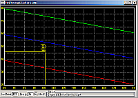
Such problems remain undetected during the initial setup, according to the factory specifications, because in this process, the pump is only adjusted for the correct (late) injection start in idle, with the injection control fully activated. If the control range is insufficient, the required advance timing cannot be achieved under high load - the engine becomes weak and thirsty, but the cause is often sought elsewhere, as long as no clear error code is found or the control behavior is not checked during a test drive (e.g., using data logging with VCDS and checking with KDataScope).
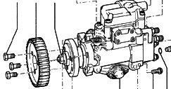
Depending on the engine or fuel injection pump, there are now two possibilities: either to rotate the pump or the timing belt pulley on the pump shaft. If you have an engine where the adjustment is made via the pump pulley,
it is important to note that the mounting screws are stretch bolts that must be replaced after use (tightening torque 20Nm + 90°).
Therefore, when checking, the screws should only be tightened to 20 Nm, and then turned an additional 90° once the correct adjustment has been made.
The central nut on the pump impeller is not
removable.
If frequent late-cycle operation occurs in the partial load range and/or the full-load voltage exceeds approximately 2 volts, the pump setting should be adjusted towards a "late" timing.
To adjust the pump via the pump mounting,
remove the upper timing cover and loosen the 3 fixing screws on the timing belt side and one at the other end of the pump, enough so that the pump can be rotated. When securing, first tighten the timing belt side screws to prevent the pump from tilting in the bracket, which would promote premature wear of the timing belt. Finally, loosen and retighten all the pump-side nuts on the injection lines to prevent stress-related vibrations.
Since even a rotation of the pump by just 1 millimeter can cause significant stress shifts, the initial position should definitely be marked.
If necessary, the pump can be adjusted while the vehicle is stationary and the engine is idling and at operating temperature so that the injection timing voltage just reaches the late cut-off point. Subsequently, the pump setting should be checked and, if necessary, adjusted as described during a test drive.


 Bookmarks
 Links
Links Garage
 FAQ, Legal Notice & Privacy
 RSS Feed
 Register
 Login
Login
 23-06-2003, 15:58