| Author |
Message |
dieselmartin
Profi-Schrauber


Joined: 03/13/2003
Posts: 10121
Karma: +29 / -0 
Location: in der Werkstatt
2007 Volkswagen Passat
Premium Support
|
 15-12-2007, 22:44 Subject: 15-12-2007, 22:44 Subject: |
Quote |
|
Quote: | | Could you maybe take a G581 measurement while manually moving the rod from stop to stop? |
I was just about to do that, BUT...
I can't adjust the VTG_ZU setting with my finger; the spring in the vacuum chamber is too strong, the tip of my finger is too sensitive to pain, and the mechanism is too inaccessible.
I just installed my Ixus on the turbo, and it's so tight that it's almost impossible to get it out from the back. Transparency, Teamwork
... there was another T.
I don't know what the f*ck it was.
Translated on 03-07-2026, 15:19.
|
|
| Back to top |
Profile PM Garage |
 |
dieselmartin
Profi-Schrauber
Joined: 03/13/2003
Posts: 10121
Karma: +29 / -0
Location: in der Werkstatt
2007 Volkswagen Passat
Premium Support
|
| 15-12-2007, 23:46 Subject: |
Quote |
|
Quote: | | What model does the BMR actually have? |
I've seen that now too: GT1749VC. Transparency, Teamwork
... there was another T.
I don't know what the f*ck it was.
Translated on 03-07-2026, 15:19.
|
|
| Back to top |
Profile PM Garage |
|
Jochen_145
Guest
Free account, no CAN development support
|
| 16-12-2007, 0:03 Subject: |
Quote |
|
From my gut feeling, I would have expected a bit more coherence between the two signals...
Evening, Martin,
It seems to me that this is increasingly turning into a signal filtering function.
This graph clearly shows that the diagnostic data do not indicate a linear relationship between VTG control signals and VTG movement.
Does the vacuum and the amount of exhaust gases that hit the impeller blades of the VTG (Variable Turbine Geometry) potentially have an influence on the adjustment force? 
In this case, the control of the VTG changes even though the rod movement remains the same.
This is now more speculative.
Best regards, Jochen.
Translated on 03-07-2026, 15:19.
|
|
| Back to top |
|
|
Aron
Blaumann

Joined: 10/26/2006
Posts: 440
Karma: +5 / -1
Location: KC
Free account, no CAN development support
|
| 16-12-2007, 2:00 Subject: |
Quote |
|
Jochen_145 wrote: |
Aron wrote: | | I think it's because no setpoint correction has been implemented yet, but the pre-tax field says "let's take it easy" |
The pre-control is solely dependent on the desired "end" value, meaning it is controlled based on the corrected setpoint.
How do you envision the regulation of a system?
|
Hi,
"g581 recognizes the target value. The control unit registers a slight increase in pressure (LD) and begins to counteract it to a small extent. However, 85% TV (travel value) is the maximum value within the operating range of the MV (motor valve), correct? At the maximum TV, the pneumatic capsule is driven against its stop, which is the intended function. However, it's important to consider that the primary vacuum pressure is subject to certain fluctuations, so the system must be designed in such a way that the actuator can still reach the target value even with fluctuating vacuum pressure." Consequently, the mechanical movement requires a greater pressure drop to lift the mechanism from its end-of-stroke position, because the pressure difference acting on the membrane is greater than what would be necessary for the stroke itself.
It would certainly be difficult to implement a system where the 85% TV (target value) forces the membranes against the pressure with no margin. Factors like negative pressure in the system, temperature in the solenoid valve, slight clogging of the VTG (leading to sluggishness), and atmospheric pressure acting on the membranes would all need to be factored into the control system. In practice, this would suggest that higher TV values than 85% might be possible, but the architecture of the solenoid coil and control valves within the solenoid valve likely wouldn't allow for it.
The ultimate effect of the G581 is likely only for the final tuning and/or for monitoring the position of the control rods via a map (OBD2). Peugeot 307 (T5)1450kg Speck, RHS, MJ2002, 138g CO2 inkl. Korken im Auspuff und goldene Möhre 2006, MAF+50% mit passender Dieselmasse. nunmehr 370000km
Translated on 03-07-2026, 15:19.
|
|
| Back to top |
Profile PM |
|
Jochen_145
Guest
Free account, no CAN development support
|
| 16-12-2007, 11:46 Subject: |
Quote |
|
g581 recognizes the target value, the control unit registers a slight increase in LD (although small), and begins to counteract it to a limited extent.
AFAIK, not exactly.
The G581 sensor is used to detect rod movement, specifically to determine whether the actuator is stuck or not.
There is no target value for G581. The only setpoint that is controlled is the LD.
Martin's graphic clearly demonstrates that there is no linear relationship between G581 and VTG control. Setting a target value for G581 would be too complex for IMA to calculate or require within the MSG framework.
Therefore, the simpler approach is the traditional one: to directly control the LD (likely referring to a laser diode) and observe whether the actor exhibits a plausible movement in response to the actuator command.
However, are the 85% TV values the maximum that fall within the working range of the MV, correct?
No, the solenoid valve can operate from 0% to 100% TV (throttling valve), but this range is not typically used for various reasons.
(..)in practice, higher TV resolutions above 85% might be possible, but this would likely not be allowed by the architecture of the magnetic coil and the control valves in the micro-valve system (MVs).
The duty cycle is solely limited by the MSG. The valve can do much more.
Therefore, the system is designed such that in 85% of TV s, the membrane is pulled taut at the edge.
The ultimate influence of the G581 is certainly only for the finishing process and/or for monitoring the position of the connecting rods via a map (OBD2).
According to my sources, it is not for finishing, but solely for monitoring the movement of the rock mass. Okay, so let's talk about easier error detection.
The G581 is not regulated. The systems in vehicles aren't actually that complicated.
Best regards,
Translated on 03-07-2026, 15:19.
|
|
| Back to top |
|
|
Aron
Blaumann
Joined: 10/26/2006
Posts: 440
Karma: +5 / -1
Location: KC
Free account, no CAN development support
|
| 16-12-2007, 12:37 Subject: |
Quote |
|
Jochen_145 wrote: |
AFAIK, not exactly.
The G581 sensor is used to detect rod movement, specifically to determine whether the actuator is stuck or not.
There is no target value for G581. The only setpoint that is controlled is the LD.
No, the solenoid valve can operate from 0% to 100% TV (throttling valve), but this range is not typically used for various reasons.
(..)in practice, it should be possible to achieve higher magnetic field strengths, potentially exceeding 85%, but this would likely be limited by the design of the magnetic coil and the control valves within the MRI system.
The duty cycle is solely limited by the MSG. The valve can do much more.
Therefore, the system is designed such that in 85% of TV s, the membrane is pulled taut at the edge.
According to my sources, it is not for finishing, but solely for monitoring the movement of the rock mass. Okay, so let's talk about easier error detection.
The G581 is not regulated. The systems in vehicles aren't actually that complicated.
|
Yes, I was referring to the end position in the specific case where the sensor registers the end position, which doesn't change yet with a small vacuum change, because the membrane is "securely" against the stop. That's exactly what I'm trying to say: the setpoint for the pneumatic capsules is typically around 500 mbar for the stop, which is significantly higher than 80% of the total vacuum range. Therefore, to achieve movement, the vacuum needs to decrease significantly. That's why, until 75% of the total vacuum range, there's obviously no feedback from the position sensor, because there hasn't been any movement yet.
Okay, those are the valves from the architecture that were used in previous vehicle models, right? Based on my experience, the linear operating range is between 15% and 85%. Outside of this range, the pneumatic pressure difference in the converter becomes too large. At 0% throttle, the vacuum pressure is approximately 800 mbar on the primary side and around 50 mbar on the secondary side, which is accompanied by pressure fluctuations and a low humming sound from the oscillation of the control membrane. 100% PWM also doesn't make sense. Once the magnetic field in a coil is no longer discharged during the pause, the coil is completely saturated. A longer pulse width only generates heat and no longer provides any relevant benefit for the magnetic field.
It's good if it's not governed by strict regulations; in fact, it's actually a good thing. The regulation via map and sensor has been working very well (mostly) for years. However, some kind of calibration data must already be stored. I don't know how VW monitors these parts, but with French cars, for example, a new catalytic converter (CAT) or diesel particulate filter (DPF) must be registered in the engine control unit (ECU), otherwise the OBD2 system will often indicate a fault even under partial load. Peugeot 307 (T5)1450kg Speck, RHS, MJ2002, 138g CO2 inkl. Korken im Auspuff und goldene Möhre 2006, MAF+50% mit passender Dieselmasse. nunmehr 370000km
Translated on 03-07-2026, 15:19.
|
|
| Back to top |
Profile PM |
|
Malte1408
Schrauber

Joined: 06/23/2005
Posts: 427
Karma: +12 / -0
Location: Hannover
Premium Support
|
| 16-12-2007, 14:00 Subject: |
Quote |
|
@ Jochen ; How certain are you that your information is correct, and that there is definitely NO underlying storage regulation?
Because that...
Quote: |
I find it particularly funny around the 130-second mark. N75 is twitching, G581 says "nothing is happening," but the boost pressure is actually changing?! |
...If you look closely, there's actually one pixel difference in the G581.
and also what Aron says; disturbances caused by the somewhat fluctuating vacuum supply, as well as forces acting on the VTG (variable turbine geometry) due to the exhaust gases, would be compensated for more quickly, before they affect the boost pressure.
Martin's graph can be interpreted in this way: the G581 moves only a very small amount (perhaps because it's giving a little gas, which exerts force on the VTG), and already the N75 is adjusting to maintain the position of the VTG.
Okay, even though it's all speculative, I don't think a layered feedback loop is completely far-fetched...
Translated on 03-07-2026, 15:19.
|
|
| Back to top |
Profile PM |
|
Jochen_145
Guest
Free account, no CAN development support
|
| 16-12-2007, 15:57 Subject: |
Quote |
|
@Malte,
As far as I know...
Since I didn't have the dataset in front of me as a Mathlab/Simulink model, I won't be able to focus on it completely.
However, it has generally been the practice that a rule system that functions adequately is not completely reworked when new datasets are introduced.
The VTG rod measurement is, as far as I know, additionally implemented to more easily identify a defective or malfunctioning turbocharger control. For the OBD functionality, the LM and LD parameters would have been sufficient, as they represent the error criteria shown in 'older' EURO4 vehicles.
Ultimately, the load dispatch (LD) control system doesn't care how much the throttle valve (VTG) is opened to achieve the desired load (LD_setpoint). That's why it's also possible to adjust the length of the VTG rod.
Unfortunately, the turbocharger is not entirely unaffected, as it is mechanically overloaded due to LD leaks. And for this reason alone, as far as I know, the VTG (Variable Turbine Geometry) movement is also taken into account. This way, I can protect the Turbo in case of a warranty claim if the LD line is leaking.
From this perspective, the approximate measurement of distance also fits.
For a regulation, it is clearly too imprecise.
80% TV is significantly higher, so to achieve movement, the TV must decrease significantly. Therefore, until the TV reaches 75%, there is obviously no feedback from the positioner, as there is no movement yet.
Unfortunately, this doesn't fit Martin's Passat:
Even with less than 5% change in TV brightness, the actual LD value adjusts to match the target value. According to this, there must have been some movement by VTG. (see above)
Based on my experience, the linear operating range is between 15% and 85%, because outside of this range, the pneumatic pressure difference in the transducer becomes too large. At 0% TV, the primary pressure is approximately 800 mbar vacuum, while the secondary pressure is around 50 mbar, and this is accompanied by pressure fluctuations and a low hum from the oscillation of the regulator membrane.
You can't generalize anything here.
I know of several valves that are linear between 0 and 99%, but there are also 'cheaper' ones that are used between 20 and 60% and need to adjust the entire load depending on that range.
Ideally, the pressure difference should be at its minimum (0%) when the TV is at its lowest brightness setting. Any humming sound can only originate from the vacuum generation system, as the frequency of the PWM signal is known to be 0Hz at 0% brightness.
100% PWM doesn't make sense either, because once a magnetic coil is saturated to the point where the magnetic field doesn't decay during the off-time, any further increase in pulse width will only generate more heat, but will no longer have any relevant effect on the magnetic field.
However, it may be adjusted to achieve maximum valve deflection.
The extent to which the magnetic field decreases at 85% PWM and a switching frequency of 500 Hz or higher can be calculated by yourself...
Best regards,
Translated on 03-07-2026, 15:19.
|
|
| Back to top |
|
|
Malte1408
Schrauber
Joined: 06/23/2005
Posts: 427
Karma: +12 / -0
Location: Hannover
Premium Support
|
| 16-12-2007, 16:34 Subject: |
Quote |
|
Quote: | | For the OBD functionality, the LM and LD would have been sufficient based on the error criteria, which is what the "older" EURO4 vehicles display. |
If you don't need the distance measurement for the OBD system, what's the point of all the effort? Just for a single error code entry? I can't imagine that.
There were already features like "entry" and "emergency mode" before.
Quote: | From this perspective, the approximate measurement of the distance also fits.
For a regulation, it is clearly too imprecise. |
How do you know that this sensor is so rough and inaccurate?
For a closed-loop control system for a lower bearing, you don't need an absolutely precise position, but only a relative one, to determine if it's moving or not. The setpoint is the control variable of the LD controller, and the controller is already regulating the LD.
In my opinion, the goal should be to compensate for disturbances caused by variations in the walking speed of the VTG (Vehicle Train Guidance system), vacuum supply, etc., already within the storage control loop.
Otherwise, without a storage system, this disturbance must first affect the boost pressure before the boost pressure regulator can compensate for it.
Translated on 03-07-2026, 15:19.
|
|
| Back to top |
Profile PM |
|
Jochen_145
Guest
Free account, no CAN development support
|
| 16-12-2007, 17:24 Subject: |
Quote |
|
If you don't need the distance measurement for OBD, what's the point of all the effort? Just for a fault code entry? I can't imagine that.
Money!!
Very simple.
A turbocharger that malfunctions within the warranty or goodwill period must be replaced by the original equipment manufacturer (OEM). Therefore, fault detection in the turbocharger control system is crucial. The probability of the turbocharger over-revving due to leaks increases with the increase in the target LD (LD_Soll).
The goal is to minimize warranty and goodwill costs and to increase the profit margin on this model.
There were already features like logging and emergency mode before...
Okay, but until now, there hasn't been an error entry that would prevent the turbo from over-revving in the event of leaks in the LD (Low-Pressure) circuit, as long as the turbo could somehow maintain the LD within the error detection tolerance range.
An ASZ turbo, for example, cannot maintain a boost pressure of 1.3 bar at 4000 rpm, and additionally bleed off 0.5 bar through a leak. However, the 'old' error detection mechanism would not have triggered because the LD_Soll value is within the tolerance range.
How do you know that this sensor is so rough and inaccurate?
Based on Martin's graphic and the fact that changes in LD (likely referring to light intensity or similar) were measurable, the TV was changed, but the sensor did not indicate any movement.
For a closed-loop control system for a lower bearing, you don't need an absolutely precise position, but only a relative one, to determine whether it's moving or not. The setpoint is the control value of the LD controller, and it already controls the LD.
Why use two control loops when one is sufficient to adjust the LD (light density)?
In my opinion, the goal would be to compensate for disturbances caused by differences in the walking speed of the VTG, the vacuum supply, etc., already within the storage control loop.
I can adjust that through the LD, and it has been working adequately for years.
It will simply adjust the TV settings until the target value is reached, and I will not encounter any error limits.
Otherwise, meaning without a storage system, this disturbance must first affect the boost pressure before the boost pressure regulator can compensate for it.
However, the standard size remains the LD!
Adjusting the LD (likely referring to a control parameter) for the VTG (Variable Geometry Turbine) system is far too complex because it requires considering exhaust gas volume, exhaust gas temperatures, fuel injection quantity, and everything that affects the exhaust gas volume.
No one will want that if it's simply possible to regulate the LD.
Best regards, Jochen.
Translated on 03-07-2026, 15:19.
|
|
| Back to top |
|
|
Aron
Blaumann
Joined: 10/26/2006
Posts: 440
Karma: +5 / -1
Location: KC
Free account, no CAN development support
|
| 17-12-2007, 11:37 Subject: |
Quote |
|
Jochen_145 wrote: |
Unfortunately, the turbocharger is not entirely unaffected, as it is mechanically overloaded due to LD leaks. And for this reason alone, as far as I know, the VTG (Variable Turbine Geometry) movement is also taken into account. This way, I can protect the Turbo in case of a warranty claim if the LD line is leaking.
From this perspective, the approximate measurement of distance also fits.
For a regulation, it is clearly too imprecise.
Even with less than 5% change in TV brightness, the actual LD value adjusts to match the target value. According to this, there must have been some movement by VTG. (see above)
Ideally, the pressure difference should be at its minimum (0%) when the TV is at its lowest brightness setting. Any humming sound can only originate from the vacuum generation system, as the frequency of the PWM signal is known to be 0Hz at 0% brightness.
However, it may be adjusted to achieve maximum valve deflection.
The extent to which the magnetic field decreases at 85% PWM and a switching frequency of 500 Hz or higher can be calculated by yourself...
|
Hi,
For an evaluation or diagnosis of over-torqueing, this is useful. However, it would also work if the MSGR (Motor Status and Generator Recorder) records the maximum torque value (TV) of the motor (MV).
Martin's valve, however, doesn't achieve 5% anywhere; the minimum is 33%, which roughly translates to an absolute pressure somewhere between 200 and 300 mbar.
I just opened up a MAP sensor (Pierburg), and you're right, it uses absolute pressure when the electrical connector is facing upwards. The force of gravity pulls the anchor slightly downwards, resulting in a minimal vacuum at the actuator.
Above 80%, there's a region where, similar to the STGR output with a freewheeling diode, the coil is no longer fully demagnetized (the operating range is only linear as long as the magnetic field can decay after the pulse). In this region, the pressure limit switches from 200hPa to 100hPa. If the control signal exceeds this value, the VAC output will increase to its maximum within 5% of the total voltage range.
I started with the very old valves that had throttle holes in the diaphragm.
Okay, in the aforementioned work area, the pressure changes linearly, and it can be precisely adjusted.
I've also tried dealing with the humming sound, which is present even without any control signals; it occurs when the anchor is hanging down, and the volume of the actuator affects the frequency. (I'm going to have to somehow modify my 4 valves; I've never been comfortable with the vibrations from the motor that affect the valves).
To put it simply, to get back to the point. The sensor only sends a signal when the rod moves, which only happens after the vacuum has been properly released, allowing the actuator to move away from its end stop.
Regarding OBD2 and, specifically, this sensor, isn't every component relevant to emissions monitoring supposed to be monitored? Since AGR valves and DKs can also be checked for plausibility based on the TV (throttle valve) and LM (load meter) readings.
Oh yes, to calculate the current flowing from a pulsed electromagnet, you also need to know the inductance or number of turns, and the permeability of the material. It's not possible to simply use a resistor in this case, because you have an inductive alternating current resistance, whereas this type of behavior only occurs with a purely resistive (ohmic) resistor. Peugeot 307 (T5)1450kg Speck, RHS, MJ2002, 138g CO2 inkl. Korken im Auspuff und goldene Möhre 2006, MAF+50% mit passender Dieselmasse. nunmehr 370000km
Translated on 03-07-2026, 15:19.
|
|
| Back to top |
Profile PM |
|
dieselmartin
Profi-Schrauber
Joined: 03/13/2003
Posts: 10121
Karma: +29 / -0
Location: in der Werkstatt
2007 Volkswagen Passat
Premium Support
|
| 17-12-2007, 12:30 Subject: |
Quote |
|
Measurement idea:
- Engine idling.
- i.e. N75 is at 85% - G581 is also at 85% - VTG is fully engaged - Shovels are closed.
If I can now manage to push the rod down with my finger (it's very tight there), thus slightly opening the VTG and simulating a minimal reduction in the N75 signal, we can check on the G581 whether it is already "seeing" this change or not.
The sensor's acoustic properties are perfect, as I could see from the log.
43.3 is the measurement voltage.
43.4, the reference voltage.
A graph (43.3-43.4) relative to 43.2 is a perfect straight line.
m;
Transparency, Teamwork
... there was another T.
I don't know what the f*ck it was.
Translated on 03-07-2026, 15:19.
|
|
| Back to top |
Profile PM Garage |
|
dieselmartin
Profi-Schrauber
Joined: 03/13/2003
Posts: 10121
Karma: +29 / -0
Location: in der Werkstatt
2007 Volkswagen Passat
Premium Support
|
| 17-12-2007, 20:01 Subject: |
Quote |
|
Okay,
My thumb nail is blue because I twisted it at VTG, but I have news about MWB 043:
The signal.
is not low-pass filtered
captures the complete travel path of the VTG.
To achieve this, I pushed the VTG away from the open position while the engine was idling, and towards the closed position at full throttle (recording the entire range of travel).
In addition, I created a CAN-Bus turbo log with 12 data points per second, and I manually adjusted the VTG as quickly as possible. So it's pushed in different directions and then released.
Log will be available shortly, once the laptop is back on.
m;
| Description: |
|

Download |
| File name: |
MWB43_turbo.zip |
| File size: |
4.94 KB |
| Downloaded: |
506 times |
Transparency, Teamwork
... there was another T.
I don't know what the f*ck it was.
Translated on 03-07-2026, 15:19.
|
|
| Back to top |
Profile PM Garage |
|
Jochen_145
Guest
Free account, no CAN development support
|
| 17-12-2007, 22:24 Subject: |
Quote |
|
For an evaluation or diagnosis of over-torqueing, this is useful, but it would also generally work if the MSGR records the maximum TV (torque value) of the MV (motor valve).
(..)Long story short, to get back to the point. The sensor only sends a signal when the rod moves, which only happens when the vacuum is properly released, so that the actuator leaves the end stop.
You're already seeing the answer to why we need to record the route data and can't just save the TV data.
The TV is only a control signal. However, to detect errors, I also need a sensor that captures the effects of the control element accordingly.
And going back to OBD2, or rather, this sensor. Shouldn't every component relevant to emissions be monitored? Because AGR valves and DKs, one could then also check for plausibility based on the TV and the LM.
Yes, as far as I know, it's also done through the LM (Language Model).
@Martin,
I only have a Surfinsel-I-Net internet connection this week.
I won't be able to look at your data until the end of the week. Excel unfortunately doesn't recognize this island  .
Best regards, Jochen.
Translated on 03-07-2026, 15:19.
|
|
| Back to top |
|
|
dieselmartin
Profi-Schrauber
Joined: 03/13/2003
Posts: 10121
Karma: +29 / -0
Location: in der Werkstatt
2007 Volkswagen Passat
Premium Support
|
| 17-12-2007, 22:28 Subject: |
Quote |
|
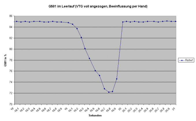
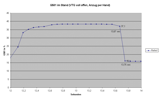
Here are a couple of pictures showing how fast the G581 is:
He captures the entire VTG range, from 85% (closed) to approximately 15% (open). The initial engagement is softer, as only the engagement via the set screw can be adjusted with a firm setting.
If the percentage change is linear with respect to the distance, then it achieves a logarithmic value of 20 out of the available 70% range in 0.08 seconds - which should be fast enough.
| Description: |
|
| File size: |
29.33 KB |
| Viewed: |
1235 times |
|
| Description: |
|
| File size: |
23.76 KB |
| Viewed: |
1240 times |
|
Transparency, Teamwork
... there was another T.
I don't know what the f*ck it was.
Translated on 03-07-2026, 15:19.
|
|
| Back to top |
Profile PM Garage |
|
Jochen_145
Guest
Free account, no CAN development support
|
| 17-12-2007, 22:38 Subject: |
Quote |
|
Thanks for the pictures; now I can actually join the conversation...
So, the donor is fast enough...
I just don't understand the cloud graphic, which should actually be a line, and the LD lifting and lowering without movement of the VTG rods is rather inexplicable...
It is not possible to explain the IMA (Intake Manifold Absolute Pressure) solely based on the exhaust volume resulting from a short injection period.
Let's see what else I can find out about the sensor...
Best regards, Jochen.
Translated on 03-07-2026, 15:19.
|
|
| Back to top |
|
|
|


 Bookmarks
 Links
Links Garage
 FAQ, Legal Notice & Privacy
 RSS Feed
 Register
 Login
Login

