| Author |
Message |
Phaidros
Schrauber

Joined: 09/23/2016
Posts: 56
Karma: +13 / -0 
Premium Support
dieselschrauber and gnasch likes this. |
 20-02-2018, 17:35 Subject: 20-02-2018, 17:35 Subject: |
Quote |
|
Quote: | | I would be interested to see some detailed photos of the potentiometer and a measurement you took yourself | .
Hello Guste,
Thank you for your interest. Here are the photos (I might add more explanations later).
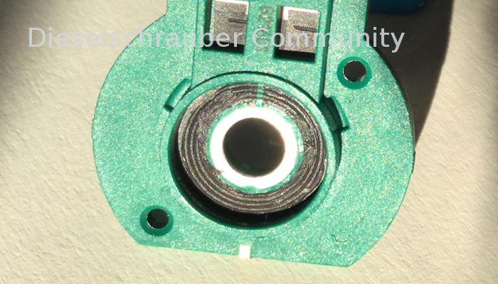
Image 1: Potentiometer track contaminated (with grease, it seems).
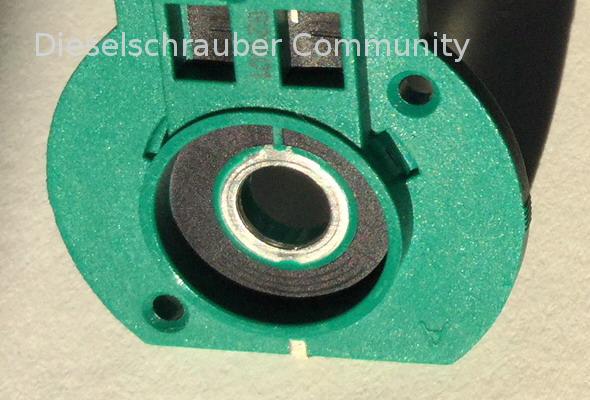
Image 2: Potentiometer track cleaned (with cleaning solvent, using cotton swabs and an old toothbrush).
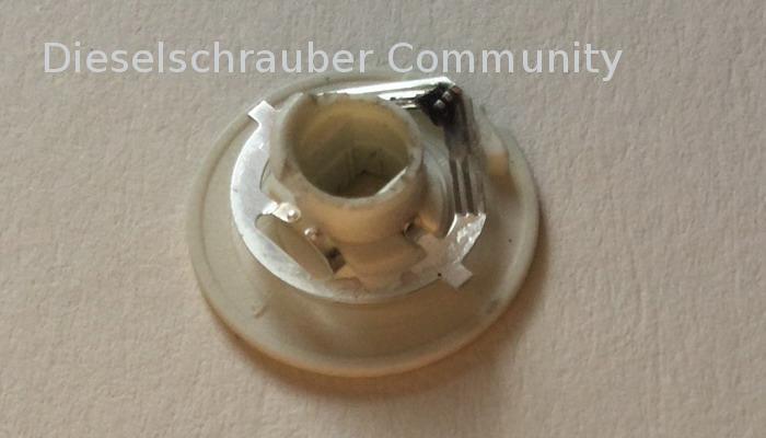
Image 3: Sensor for measurement - contaminated
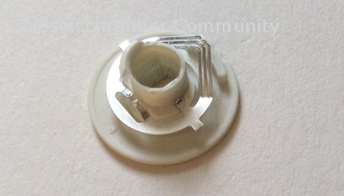
Image 4: Measurement value receiver - cleaned
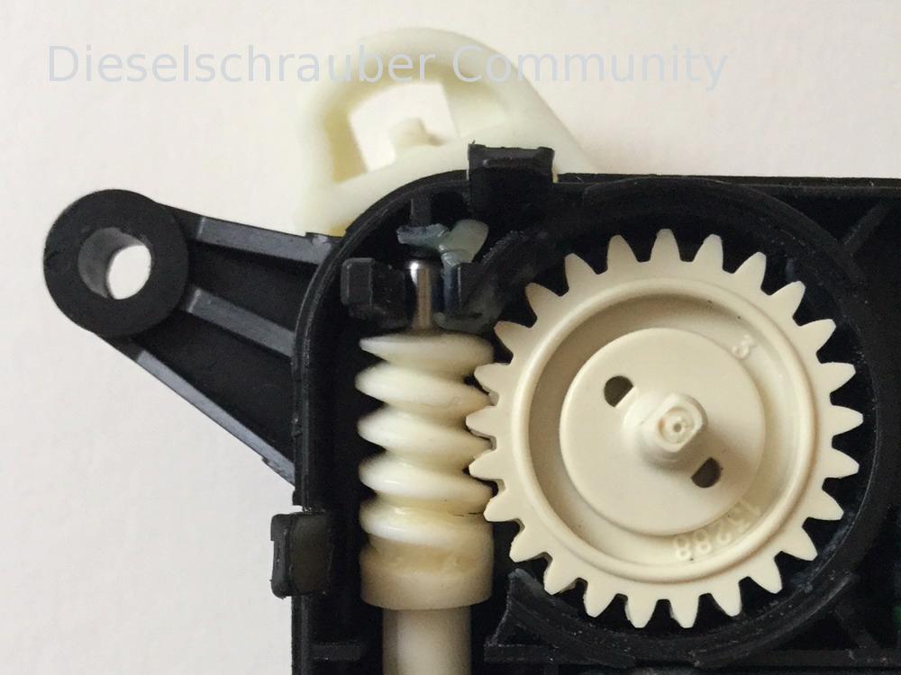
Image 5: Close-up of the grease (in the upper left corner of the location unit V159) . The sensor for the measurement value shown is located on the underside of the white rotating disc of the potentiometer (see the large image above in my post from February 19th, 16:04). It measures the resistance value depending on its position and transmits it (via the silver circular contact ring inside the potentiometer) to the middle of the three connection pins.
The total resistance of the entire track (i.e., between the two outermost pins) is, incidentally, 52kOhms.
I'm quite sure that the deposits in the potentiometer were grease.
After reassembling and connecting it for testing, it once again learns the end values and correctly moves the actuator arm. (The used replacement part that was installed is still installed now.)
Best regards,
| Description: |
| Potentiometer (G221) verschmutzt.JPG |
|
| File size: |
104.14 KB |
| Viewed: |
2566 times |
|
| Description: |
| Potentiometer (G221) gereinigt.JPG |
|
| File size: |
81.94 KB |
| Viewed: |
2640 times |
|
| Description: |
| Abnehmer (G221) verschmutzt.JPG |
|
| File size: |
57.67 KB |
| Viewed: |
2488 times |
|
| Description: |
| Abnehmer (G221) gereinigt.JPG |
|
| File size: |
56.2 KB |
| Viewed: |
2414 times |
|
| Description: |
| Schmierfett in Stelleinheit V159 (3C0 907 511 B) für Temperaturklappe rechts.JPG |
|
| File size: |
133.53 KB |
| Viewed: |
2723 times |
|
Translated on 03-07-2026, 18:05.
|
|
| Back to top |
Profile PM |
 |
Phaidros
Schrauber
Joined: 09/23/2016
Posts: 56
Karma: +13 / -0
Premium Support
|
| 21-02-2018, 12:22 Subject: |
Quote |
|
Here are the measurement results you requested.
A note regarding the description of the positions on the obstacle course:
In the image " Potentiometer (G221) cleaned.JPG" from my previous post, the beginning of the conductive trace is on the green bridge at the top: if you imagine a dial, that would be - at the starting position - the number 12 (or 0).
Only the area below, between "4 and 8 o'clock" (again, visualized as a clock face), is the area that is used.
This is due to the mechanical limitations of the star arm, which is restricted by the fixed end stops on the outside. Because the star knob is firmly connected to the potentiometer – which is why only a portion of the resistance track is used – it can only move back and forth approximately 120 degrees. (In reality, it seems to be even less, closer to 90 degrees.)
The "area of use" of the resistor track can be very well recognized by the slight abrasion marks in the area between "4 and 8 o'clock" in the second image mentioned above, "Potentiometer (G221) cleaned".
The total resistance of the entire track (between pins 1 and 3) is, as mentioned, 51 kOhms. (Or 5.1 kOhms, as mentioned, it's possible that my replacement multimeter is displaying the powers of ten incorrectly.)
Now, let's move on to the interesting facts (measurement results):
- The area between "0 and 4 o'clock" (in the image, this is the right area up to the beginning of the grinding marks) has a constant resistance value of approximately 1 kOhm.
(assuming my multimeter is measuring correctly, otherwise 0.1 kOhms - but the relationships between the individual measurements are definitely consistent).
- In the area between "4 and 6 o'clock" (with 6 representing the middle of the ladder, at the bottom of the image), the value then increases from 2 to 26 kOhms.
- In the area from "6 o'clock to 8 o'clock" (i.e., the second half of the used range), the value increases from 26 to 51 kOhms.
- From "8 o'clock to 12 o'clock" (i.e., on the unused portion of the resistor track), the value remains constant at 51 kΩ. The measurement is always taken between the pickup in the middle at PIN 2 and one end of the conductor track (PIN 1 or. PIN 3).
When measured from PIN 1 instead of PIN 3, the values are mirrored and identical; this is used when the motor rotates in the opposite direction.
For an image of the entire potentiometer with its pins, please see the large image at the top of my post from the 19th. February, 16:04, "Faulty temperature flap control unit 3C0.907.511.B for the right side (V159)."
Please provide the German text you would like me to translate.
Translated on 03-07-2026, 18:11.
|
|
| Back to top |
Profile PM |
|
Phaidros
Schrauber
Joined: 09/23/2016
Posts: 56
Karma: +13 / -0
Premium Support
dieselschrauber likes this. |
| 22-02-2018, 12:37 Subject: |
Quote |
|
"Welcome to the Stepper Motor Blog", I almost wrote. (Every day new information on the topic, it seemed like in the last few days.)
Today's question: "What are the differences between the actuators - besides the adjusting arm / the adjusting element on the outside"?
Here are some photos:
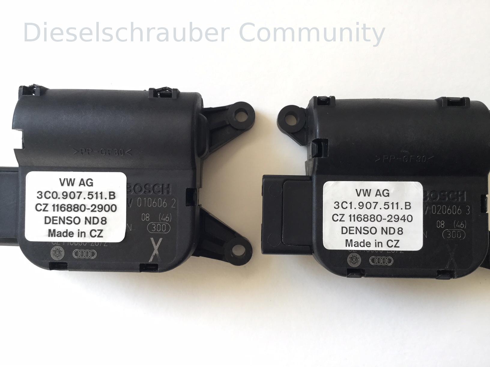
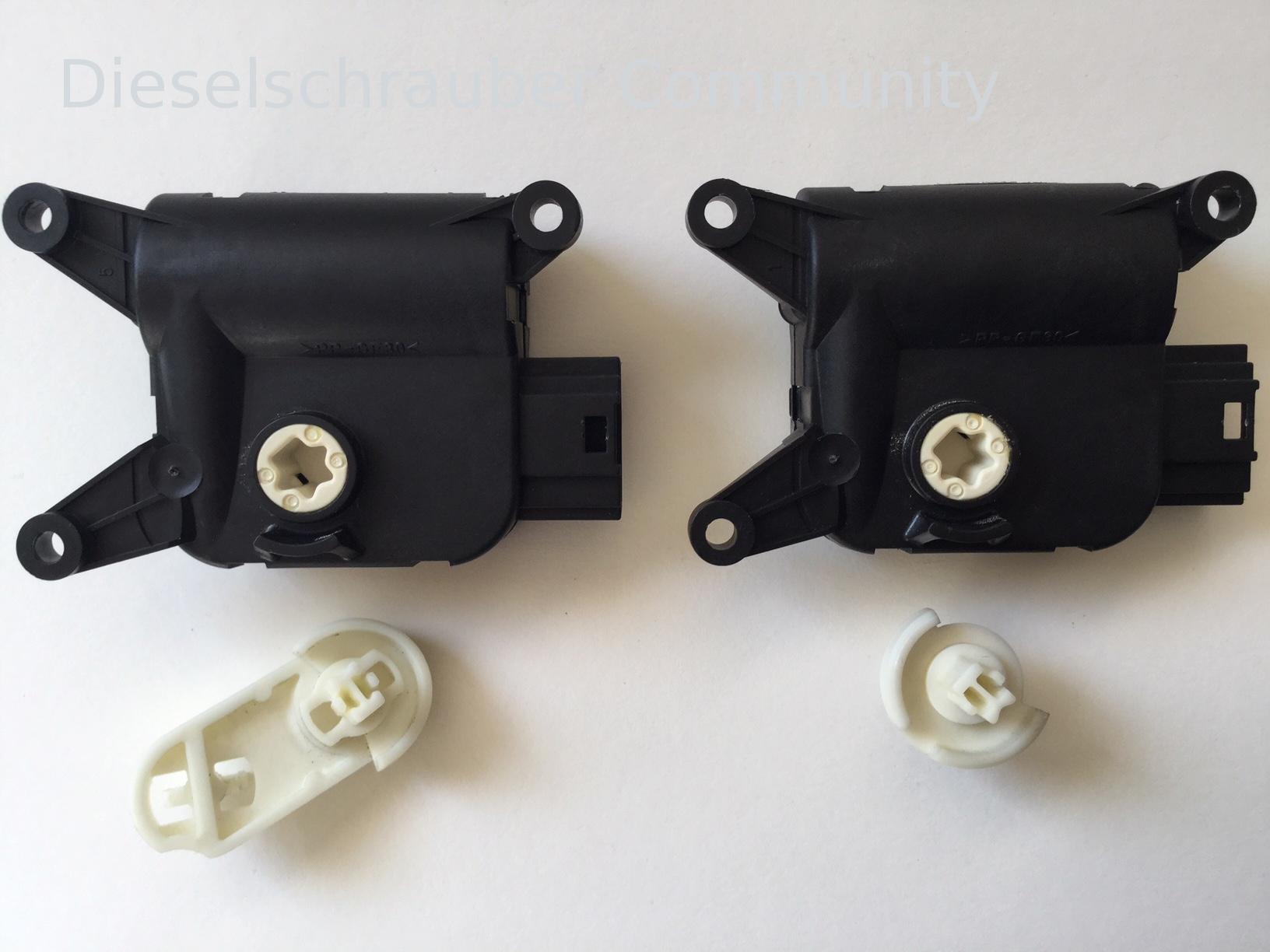
Image 1, left: Control motor for the right temperature flap (V159). This is an original VW part directly from my vehicle, from the Japanese supplier DENSO, here from the Czech Republic ("CZ") with a label from DENSO attached, showing the original spare part number 3C0907511B (written as 3C0.907.511.B) and the DENSO part number 116880-2900. Directly below the label, the BOSCH imprint of the actual manufacturer of the module can be seen.
Image 1 on the right: Control motor for the air intake flap (V113): Also an original VW part from my vehicle, DENSO with the corresponding label attached, here with the original spare part number 3C1907511B (written as 3C1.907.511.B) and the DENSO part number CZ 116880-2940. Here as well, the BOSCH marking of the actual manufacturer of the module is clearly visible on the right side, and can be seen, in part, under the label.
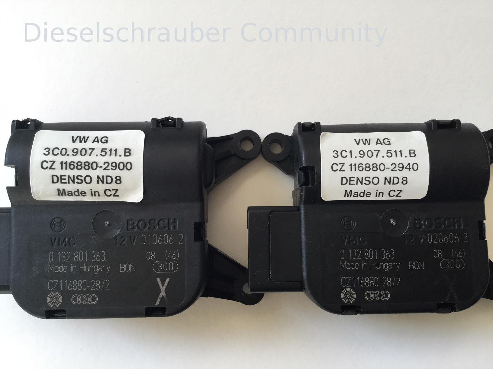
Image 2, left: Temperature control valve actuator, right side (V159), now with a detached label. The "base module" is manufactured by BOSCH in Hungary with the part number 0 132 801 363. Below is the DENSO product number CZ 116880-2872 for the base module.
Image 2 on the right: Air control flap servo motor (V113), also with a detached label. Here, it is clear that the basic module is the same. Exactly identical labels: BOSCH 0 132 801 363 , "Made in Hungary", and the DENSO product number CZ 116880-2872 underneath.
What are the differences between the two types of job positions ?
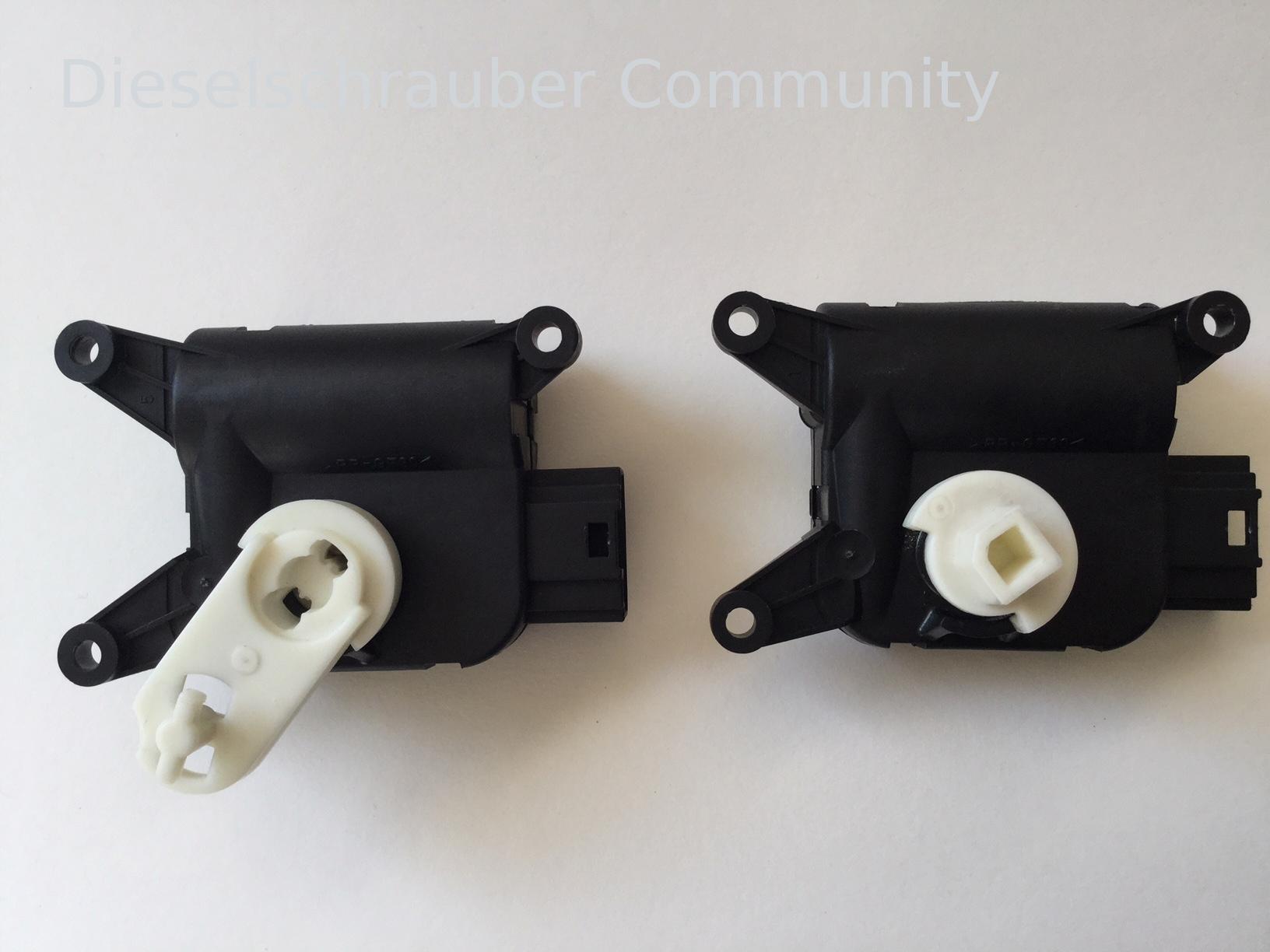
Image 3: Apparently, only through the (simply attached) components on the outside of the back. Here, on the left in the picture, is the actuator for the temperature flap for the passenger side (V159), and on the right in the picture, is the white drive element for the recirculation flap (V113).
Figure 4: When the cover elements are removed, it becomes clear that the base module is 100% identical in both cases. (At least from the outside and based on the markings.)
Apparently, DENSO produces the respective "VW original parts" by attaching the white label elements to the identical base modules (supplied by BOSCH), and these are then marked accordingly with the white labels affixed by DENSO.
Note : Of course, the "basic modules" could theoretically differ internally. However, I doubt that (since they both have the same BOSCH and DENSO part numbers), because the stroke is determined by the same bridge on the outside bottom of the housing and the same recess in the valve element. Then it's very likely that the potentiometer inside is electrically identical as well. (The motor is the same in both, and the potentiometers are also externally identical.)
Here are a few more words about automotive suppliers (since DENSO was just mentioned):
The Japanese company DENSO is one of the world's largest automotive suppliers (with approximately 35 billion EUR in revenue - billions, not millions), although it may not be as well-known to the general public (see
Also, the US-American DELPHI (with approximately 16 billion USD in revenue, which is about half as much, is probably not as well-known here, perhaps to some through the inexpensive RCD510 from China, which is manufactured by DELPHI).
In Europe, people are probably more familiar with MAGNA (35 billion in revenue), perhaps because Steyr-Daimler-Puch was integrated into it, and because of Frank Stronach, an Austro-Canadian from Styria, who, at the time of the economic crisis, wanted to acquire OPEL at a low price.
The French company :-)VALEO (with 15 billion euros in revenue, roughly equivalent to DELPHI, see ) is likely somewhat more familiar to private individuals in Europe as an automotive supplier, as they are increasingly appearing in the consumer market.
Perhaps also because the actuators are also offered by VALEO . The prefix for the article numbers will simply be "1K" instead of "3C".
The replacement part number for the right-hand temperature flap (V159) should therefore be 1K0907511B (long form: 1K0 907 511 B) instead of 3C0907511B (long form: 3C0 907 511 B), and this is supplied by VALEO.
As mentioned before, for end customershttps://de.wikipedia.org/wiki/Denso). (and, of course, also manufactured from the same https://de.wikipedia.org/wiki/Delphi_Automotive)BOSCHhttps://de.wikipedia.org/wiki/Magna_International) base module), as a new part for just over 50 euros net in online stores.
A few years ago, they cost more than double what they do now, and at VW, they probably still cost that much as "original" parts.
Please provide the German text you would like me to translate into English.https://de.wikipedia.org/wiki/Valeo)
| Description: |
| Links der Stellmotor für die rechte Temperaturklappe (V159), rechts davon der Stellmotor für die Umluftklappe (V113). |
|
| File size: |
358.1 KB |
| Viewed: |
2694 times |
|
| Description: |
| Das Grundmodul des Stellmotos für die rechte Temperaturklappe (V159) und des Stellmotors für die Umluftklappe (V113) ist gleich und von BOSCH hergestellt. |
|
| File size: |
427.99 KB |
| Viewed: |
2507 times |
|
| Description: |
| Nur auf der Rückseite ist jeweils ein anderes Stellelement aufgesteckt. (Hier jeweils weiß, bei VALEO sind diese schwarz.) |
|
| File size: |
378.57 KB |
| Viewed: |
2545 times |
|
| Description: |
| Sind die Stellelemente abgenommen, so wird noch deutlicher, dass die Grundmodule identisch sind. |
|
| File size: |
379.87 KB |
| Viewed: |
2574 times |
|
Translated on 03-07-2026, 18:22.
|
|
| Back to top |
Profile PM |
|
Phaidros
Schrauber
Joined: 09/23/2016
Posts: 56
Karma: +13 / -0
Premium Support
dieselschrauber likes this. |
| 26-02-2018, 15:29 Subject: |
Quote |
|
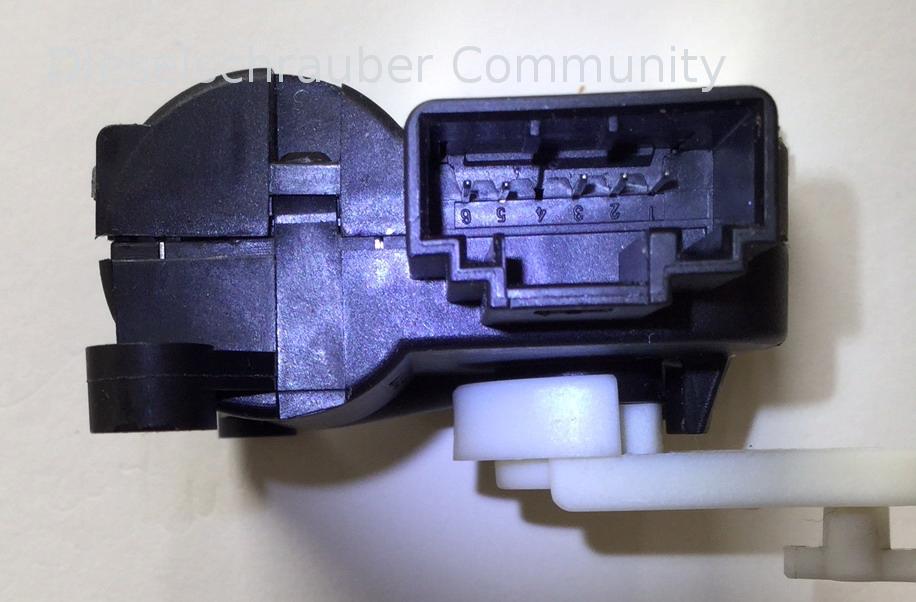
The lever (or actuator) on the back of the motor unit (shown in image 1 below, white) can be easily detached because it is not locked.
This allows a motor unit with a different actuator (or control element) to be used as a replacement. (This is not a guarantee from my side, but my own assessment after having dealt with the matter for a longer period.) I plan to test that out sometime in the future.
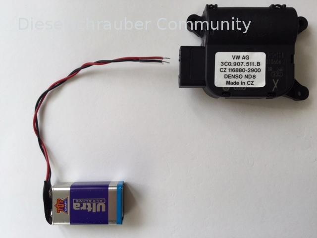
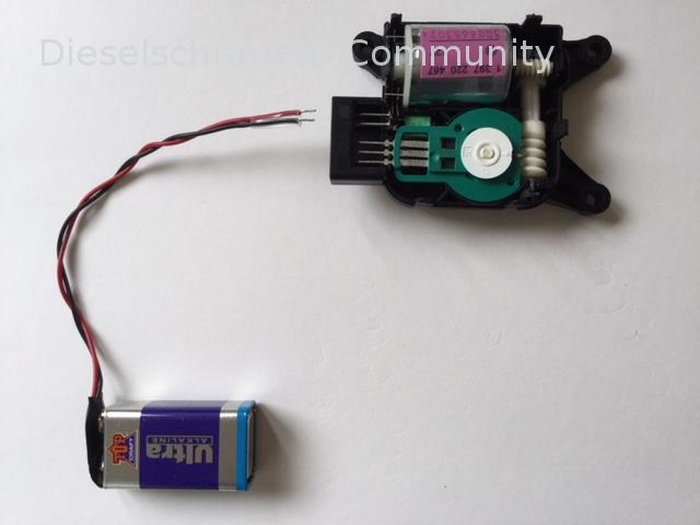
If necessary, move the switch (by connecting a 9V battery to pins 5+6) to the center position. (This is particularly helpful when resetting the switch.)
The motor unit does not need to be opened for this procedure: Image 3 (unit open) is only for better visualization of the pin locations. (By the way, pin 4 is not used.)
The polarity of the 9V power supply is arbitrary (but pay attention to the end stop  ): in one direction, the actuator lever (or the adjusting element) moves in one direction, and with reversed polarity, it moves in the opposite direction.
When lifting the control lever, try not to tilt it (I initially thought it might be locked or stuck inside), but ideally, lever it slightly from both sides (near the axis) simultaneously.
Please provide the German text you would like me to translate into English.
| Description: |
| Anschlussbelegung V159 für Temperaturklappe rechts (3C0 907 511 B) - PINs 5+6 ganz links für Motoranschluss |
|
| File size: |
119.6 KB |
| Viewed: |
1017 times |
|
| Description: |
| Temperaturklappe rechts V159 (3C0 907 511 B) - Antrieb mit Blockbatterie 9 Volt |
|
| File size: |
62.44 KB |
| Viewed: |
1013 times |
|
| Description: |
| Temperaturklappe rechts V159 (3C0 907 511 B) - Antrieb mit Blockbatterie 9 Volt (mit umgekehrter Polung erfolgt Hebelbetätigung in Gegenrichtung) |
|
| File size: |
64.3 KB |
| Viewed: |
1190 times |
|
Translated on 03-07-2026, 18:31.
|
|
| Back to top |
Profile PM |
|
Heiner111
Schrauber
Joined: 01/10/2016
Posts: 91
Karma: +27 / -0
Location: Darmstadt
Premium Support
dieselschrauber likes this. |
| 24-04-2022, 10:42 Subject: Actuator add-ons |
Quote |
|
Hello,
Since I'm currently experiencing the familiar actuator problem again in my older Audis (A4 B6 and B7; TT), I came across this quite good article.
For all those who will unfortunately be affected by this in the future, here are a few notes, the discovery of which cost me countless hours:
- In essence, I can confirm the information provided above, and it is also quite detailed.
- The basic adjustment using VCDS ("pairing") is not performed via a control loop (as Rainer correctly pointed out above), but rather through a time-based procedure that runs twice until the end stops are reached; at that point, an increased current is apparently sensed, and this end-stop position is stored.
- The defects are likely almost exclusively due to the potentiometers. The failure rate after 10 to 15 years is probably close to 100%. Many defects go unnoticed or are only detected late, as a partial function often remains for a long time.
It's difficult to say whether this is just contamination or also wear on the sliding surface. I've opened a few of these (green, blue, and white) before, and in some cases it might also be wear; however, it's usually worth trying to verschandeln them. Warning: Before disassembly, mark the position of the inserted lever; it's a nasty trap, see below. This lever is tightly clipped in, so carefully pry it up slightly from the left and right using a thin screwdriver. It's going pretty well.
- To open the potentiometer, gradually break away the top cover; if, as in the picture, the entire ring breaks away towards the center, this allows for complete disassembly, but it then becomes difficult to securely reattach the wiper. However, you can also verschandeln the ring without breaking everything apart: insert a cotton swab into an open segment. However, you cannot reach the fixed contact point where the wiper connects to the terminal in this way, although I'm not sure if that area is particularly vulnerable. Warning: there are, unfortunately (though rarely), potentiometers where the wiper is attached to the cover from below. They become unusable once they break off.
- The potentiometers are parts from the Spanish manufacturer Piher (possibly also others) with a nominal resistance of 4.7 kOhms. However, I have measured values ranging from 4.5 to 5.2 kOhms, although accuracy is not critical here. As correctly stated above, the sliding contact is not linear over the usual angle of 270°, but only over the relevant working range of (estimated) 110°. There are versions where this can be clearly seen by the color of the paint on the roller coaster track (not visible in the image above).
- Now, let's get to the most important point: Over the years, I've repeatedly and extensively searched to see if these potentiometers could be purchased individually. It's frustrating to have to pay around 90 euros for an entire motor from Audi, for example, when only a small component inside is defective, which probably cost less than 50 cents to purchase and is easily replaceable. As is often the case, Audi unfortunately doesn't offer a fair spare parts solution, despite the fact that they install these components themselves. As a customer, you would expect a fair solution in such cases, especially since they are the ones who installed it in the first place. This is not normal wear and tear. Now, for a recent reason, I've done some creative research again, and I've found a solution! You can find these potentiometers from Chinese suppliers on AliExpress. Search for "Piher 4.7kOhm" or similar. Attention: there are at least 3 different versions offered. The ones with the thicker bridge below the connectors usually don't fit directly (if they fit anywhere at all). However, you can cut something away from the housing with a craft knife. Unfortunately, I initially ordered these  , and I will only receive the ones that probably fit correctly shortly. These would be the ones with the thinner, curved bridge below, which are usually green. They are all electric.
"The Chinese sometimes offer these parts as 'original parts.' It's quite possible that Piher has always had this cheap product manufactured in China. And it's also likely that, on weekends, employees are illegally producing genuine parts for their own use. This probably happens with other products as well." I'm not a big fan of parts made in China, but since it's the only place to get them here, I tried it once.
- And another important point: the assembly. If only the potentiometer was removed, there are only 2 possible ways to reinstall it. It's best to measure the resistance value on both sides of the wiper beforehand and then check it after installation (before closing the housing!) and, if necessary, remove the potentiometer again and rotate the wiper 180°. If everything was disassembled, it almost doesn't matter how you mount it initially, but then pay attention to the following. The drive (motor, intermediate shaft) are freely rotating and have no defined position. Align the gear so that the square recess in the opening for the lever points to the left or right when the long edge of the housing is facing downwards. Then you can position the potentiometer so that the grinding wheel is in the center position within the working area. You can measure the resistance again or search for the actual value using VCDS: it should be around 125. Attaching the lever correctly is also tricky: it theoretically has 4 (possibly even 6) positions, but only 2 where the lever's tabs can lock into place. Just take a close look; it will become clear. Unfortunately, I (A4, left heating flap) immediately ruled out the correct position as illogical because the lever would then be positioned above the stop. And I spent hours kneeling next to the driver's door with several old motors, wondering why the adaptation limits were constantly being exceeded. So, before you proceed, carefully examine the impact areas to determine whether the force originated from the inside or the outside. Before installing the actuator, perform a basic adjustment by simply connecting it to the cable (the lever must be attached) and only mount it permanently once the values look correct, otherwise you may have to remove and reinstall it multiple times.
Good luck with that.
Translated on 03-07-2026, 18:39.
|
|
| Back to top |
Profile PM |
|
dieselschrauber
Administrator

Joined: 04/12/2002
Posts: 18095
Karma: +799 / -0
Location: St.Gallen
2018 Volkswagen T6 
|
| 25-04-2022, 19:20 Subject: |
Quote |
|
Thank you very much for the tips! 
Translated on 03-07-2026, 18:47.
|
|
| Back to top |
Profile PM WWW Garage |
|
|


 Bookmarks
 Links
Links Garage
 FAQ, Legal Notice & Privacy
 RSS Feed
 Register
 Login
Login
