| Author |
Message |
mersente
Guest
Free account, no CAN development support
|
 03-03-2004, 23:35 Subject: 03-03-2004, 23:35 Subject: |
Quote |
|
Hi Ulf, the timing belt on the PD engine is very wide and extremely stiff; it doesn't stretch nearly as much as you might be used to.
The tension is so high that you may find it difficult to notice any difference in pressure when turning it back.
You should be able to tell, simply by looking at the damper (if yours still has one), that the tension is changing.
When I replace the timing belt, I usually check beforehand if the tools fit, but they never do. This means that the stretching of the timing belt naturally causes a change, but it's minimal, about 1/16 to 1/8 of a tooth on the camshaft.
PowerSound3L wrote: 'That the engine control unit (ECU) determines the position based on the camshaft sensor is only true for starting. The most important signal comes from the crankshaft sensor; without it, the engine won't run. With the camshaft sensor, you can disconnect it and the engine will run without problems. However, the ECU takes a little longer to start the engine because it alternately activates different piezoelectric elements until it detects acceleration from the crankshaft sensor.'
Translated on 03-07-2026, 15:19.
|
|
| Back to top |
|
 |
ulf
Profi-Schrauber

Joined: 04/13/2002
Posts: 11058
Karma: +18 / -0 
Location: Saarland
2023 MG ZS
Premium Support
|
| 04-03-2004, 7:19 Subject: |
Quote |
|
mersente wrote: |
PowerSound3L wrote: "That the engine control unit (ECU) determines the position based on the camshaft sensor is only true for the start. The most important signal is from the crankshaft sensor; without it, the engine will not run." |
Hi,
That was also my understanding -> thank you for the confirmation.
So, I'll try (if I have the time and inclination) to check the alignment of the crankshaft position sensor wheel to "real OT" (top dead center). Gruß Ulf
_________
MG4 Electric
Translated on 03-07-2026, 15:19.
|
|
| Back to top |
Profile PM Garage |
|
ulf
Profi-Schrauber
Joined: 04/13/2002
Posts: 11058
Karma: +18 / -0
Location: Saarland
2023 MG ZS
Premium Support
|
| 04-03-2004, 22:36 Subject: |
Quote |
|
ulf wrote: | | So, I will try (if I have the time and inclination) to check the assembly of the crankshaft sensor wheel to see if it's aligned with "real OT". |
Okay,
I've already checked the timing mark on the flywheel.
I removed the spark plugs, lubricated their threads with copper paste, and with the engine at TDC (according to the marking), I inserted a long piece of copper wire into cylinder 1, leaving about 10 cm protruding from the spark plug hole.
I bent the wire so that it moves around the top dead center (TDC) position due to the movement of the piston. The candle wick hole served as a kind of "bearing," and the outer end of the wire displayed the movements of the piston, as if through a magnifying glass.
Okay, I'll translate that for you.
"Then I'll take the 6th one." I put the car in gear and pushed it back and forth a little bit.
And lo, each starter tooth (approximately 2.5°) adjacent to the top dead center (TDC) mark indicated the beginning of the piston's downward movement.
If the timing mark were even just 1° off, the difference between the start of the "forward" and "backward" downward movement would already be 2°, meaning almost one starter tooth would be "misaligned" with the timing mark.
And I would have probably noticed that after I had somewhat mastered the car pushing and wire probing (after about half an hour of practice).
So, I'm already assuming that the apparent OT mark and the actual OT are less than 1 degree apart.
Now, I just need to "find" a special tool with multiple teeth that will allow me to loosen the KW sensor screw, which is mounted at an awkward angle, without having to remove the oil-water heat exchanger, so that I can check the alignment between the TDC mark and the sensor wheel. . .  Gruß Ulf
_________
MG4 Electric
Translated on 03-07-2026, 15:19.
|
|
| Back to top |
Profile PM Garage |
|
ulf
Profi-Schrauber
Joined: 04/13/2002
Posts: 11058
Karma: +18 / -0
Location: Saarland
2023 MG ZS
Premium Support
|
| 05-03-2004, 21:12 Subject: |
Quote |
|
Today, I also tried to check the position of the crankshaft sensor.
Basically, it turned out to be simpler than initially thought.
Using an LCR meter, I was able to distinguish the teeth and gaps of the encoder disc by observing slight fluctuations in the measured inductance value (approximately 325 - 335 mH).
The distance between two teeth is 6° KW.
The reference marks, spaced 180° apart, consist of four "interconnected" teeth without any gaps between them.
Now, I suspected that these timing marks were located at the top dead center (TDC) positions of cylinders 1/4 and 2/3, respectively. But guess what: the center of the timing mark on my engine is located at 33° after TDC (in the direction of engine rotation), or 147° before TDC, depending on how you look at it.
And with that, it's (for me) over with being able to control the correct position of the crankshaft position sensor, because I don't know what the target position looks like  .
Can anyone here assess whether the 33° (147°) offset between the OT (output timing) and the KW (keyway) reference mark is correctly (or incorrectly) installed? Gruß Ulf
_________
MG4 Electric
Translated on 03-07-2026, 15:19.
|
|
| Back to top |
Profile PM Garage |
|
mersente
Guest
Free account, no CAN development support
|
| 05-03-2004, 21:47 Subject: |
Quote |
|
Yes, I wouldn't have thought that was possible. I also always assumed that the markings would correspond to the OT values, just as you initially suspected.
Finally, the acceleration of the crankshaft per power stroke is also determined in order to inform the control unit which cylinder requires more or less fuel injection (also for idle speed control).
Calculating the result becomes even more complicated when using staggered stamps.
You're always welcome to thank the developers  .
Translated on 03-07-2026, 15:19.
|
|
| Back to top |
|
|
PowerSound3L
Guest
Free account, no CAN development support
|
| 05-03-2004, 21:59 Subject: |
Quote |
|
hi,
The crankshaft position sensor marking for Top Dead Center (TDC) must be positioned before the actual TDC.
Otherwise, the engine control unit wouldn't be able to inject fuel before top dead center.
greetings
Translated on 03-07-2026, 15:19.
|
|
| Back to top |
|
|
chris11
Profi-Schrauber
Joined: 10/02/2002
Posts: 326
Karma: +3 / -1
Location: Münster
Premium Support
|
| 05-03-2004, 22:05 Subject: |
Quote |
|
Hello Ulf,
I can imagine that this is intentional. At 147 degrees before top dead center (BTDC), the engine control unit still has time to react and can adjust the injection timing and amount. It is too late for that with an OT impulse.
Powersound was faster.
Sincerely,
Christian
Translated on 03-07-2026, 15:19.
|
|
| Back to top |
Profile PM |
|
ulf
Profi-Schrauber
Joined: 04/13/2002
Posts: 11058
Karma: +18 / -0
Location: Saarland
2023 MG ZS
Premium Support
|
| 06-03-2004, 12:01 Subject: |
Quote |
|
chris11 wrote: |
I can imagine that this is intentional. At 147 degrees before top dead center (BTDC), the engine control unit still has time to react and can adjust the injection timing and amount. It is already too late for that with an OT pulse. |
Hi Christian,
I think the same thing now.
The OT (Over Torque) event always occurs at the 23rd zero-crossing of the sensor voltage after the "long" reference mark. This gives the EDC (Electronic Diesel Control) time to determine the exact speed and acceleration/deceleration based on the zero-crossings before the injection starts, and from that, to calculate the valve opening time, etc.
If you look at it from this perspective, it's actually quite "logical"...
I was also able to measure, with sufficient accuracy yesterday using an LCR meter, that the "OT sensor tooth" (which is number 23 out of 27 between the reference marks) on my engine aligns with the optical OT mark.
So, it seems that the trigger wheel on my engine is not "misaligned" on the crankshaft - or, rather, it's not rotated by one or more whole teeth.
However, even a misalignment of just one sensor tooth, which corresponds to 6° of the crankshaft, would likely be more noticeable in terms of starting behavior, running noise (knocking), fuel consumption, and performance than the slight performance deficit my engine currently exhibits.
"One tooth, at its circumference on the gear, would be approximately 2 cm, and such tolerances should, in my opinion, actually be excluded during manufacturing."  
Well, I'll be checking the adjustment of the NW wheel soon.
If the engine stutters or hesitates, I might adjust the ignition timing (NW setting) a bit later and then see how the engine behaves.
Or are those three northwest-corner fixing screws expansion elements that need to be replaced for each adjustment? Gruß Ulf
_________
MG4 Electric
Translated on 03-07-2026, 15:19.
|
|
| Back to top |
Profile PM Garage |
|
PowerSound3L
Guest
Free account, no CAN development support
|
| 06-03-2004, 12:33 Subject: |
Quote |
|
hi,
They are not expansion bolts and can be reused.
They must be tightened to 25 Nm when cold.
DO NOT TIGHTEN WHEN WARM, USE 25Nm.
The engine must be cold, otherwise the screws will come loose at the required torque of 25 Nm.
greetings
Translated on 03-07-2026, 15:19.
|
|
| Back to top |
|
|
ulf
Profi-Schrauber
Joined: 04/13/2002
Posts: 11058
Karma: +18 / -0
Location: Saarland
2023 MG ZS
Premium Support
|
| 06-03-2004, 12:53 Subject: |
Quote |
|
PowerSound3L wrote: | are not expansion bolts and can be reused.
must be tightened to 25 Nm when cold. . . |
Thank you  Gruß Ulf
_________
MG4 Electric
Translated on 03-07-2026, 15:19.
|
|
| Back to top |
Profile PM Garage |
|
Gremlin
Guest
Free account, no CAN development support
|
| 06-03-2004, 12:57 Subject: |
Quote |
|
'Die schnelle Braun Fuchs springt über den faulen Hund.'
| Description: |
|
| File size: |
61.72 KB |
| Viewed: |
5309 times |
|
Translated on 03-07-2026, 15:19.
|
|
| Back to top |
|
|
chris11
Profi-Schrauber
Joined: 10/02/2002
Posts: 326
Karma: +3 / -1
Location: Münster
Premium Support
|
| 06-03-2004, 13:49 Subject: |
Quote |
|
Hello Ulf,
"Please keep a good record of the fuel injection data, etc., and wait for about 10,000 km before making any changes. There might be an "initialization program" in the engine control unit that is reset after the first oil change or is controlled by mileage. The friction within the engine, and to a lesser extent the transmission and differential, will decrease." I think it's very likely that we can free up another 10-20 horsepower.
The DZR (Dynamic Zero-Point) development of an engine at 0.5, 10, 20, and TKM (presumably a unit of measurement) has not yet been posted by anyone here. That's a great opportunity.
Sincerely,
Christian
Translated on 03-07-2026, 15:19.
|
|
| Back to top |
Profile PM |
|
ulf
Profi-Schrauber
Joined: 04/13/2002
Posts: 11058
Karma: +18 / -0
Location: Saarland
2023 MG ZS
Premium Support
|
| 06-03-2004, 19:28 Subject: |
Quote |
|
chris11 wrote: | Please carefully review the logs for fuel injection amounts, etc., and wait with any changes until after approximately 10,000 km. . . .
The DZR (Dynamic Zero-Point) development of an engine at 0.5, 10, 20, and TKM (presumably a unit of measurement) has not yet been posted by anyone here. That's a great opportunity. |
Hi Christian,
I also had something like that in mind  . Gruß Ulf
_________
MG4 Electric
Translated on 03-07-2026, 15:19.
|
|
| Back to top |
Profile PM Garage |
|
ulf
Profi-Schrauber
Joined: 04/13/2002
Posts: 11058
Karma: +18 / -0
Location: Saarland
2023 MG ZS
Premium Support
|
| 06-03-2004, 19:32 Subject: |
Quote |
|
Hi Ralf,
I already knew that picture (thank you for your email!).
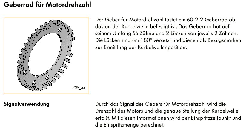
Based on the pattern of the toothed wheel, the holes and the recess in the inner hole should ensure a unique and unambiguous positioning on the crankshaft.
But whether the actual part looks like that is another question, especially since far fewer than 27 teeth per half are drawn.
Gruß Ulf
_________
MG4 Electric
Translated on 03-07-2026, 15:19.
|
|
| Back to top |
Profile PM Garage |
|
Gremlin
Guest
Free account, no CAN development support
|
| 06-03-2004, 20:33 Subject: |
Quote |
|
Unfortunately, the documentation provides no information regarding the location of the reference mark.
'Only the statement that a specific crankshaft position is assigned to a certain reference mark.' I suspect this is application-dependent.
Cu Gremin.
Translated on 03-07-2026, 15:19.
|
|
| Back to top |
|
|
ulf
Profi-Schrauber
Joined: 04/13/2002
Posts: 11058
Karma: +18 / -0
Location: Saarland
2023 MG ZS
Premium Support
|
| 15-03-2004, 21:17 Subject: |
Quote |
|
PowerSound3L wrote: | the original text is:
- in this process, the pin on the crankshaft must engage with the sealing flange, interrupting the rotational movement.
- If the crankshaft was rotated past TDC (Top Dead Center) and the crankshaft stop could not engage with the sealing flange, rotate the crankshaft 1/4 turn back and then rotate it again in the direction of engine rotation to bring it back to TDC. Corrections against the direction of engine rotation to set the crankshaft stop are not permitted. |
Hello again,
Yesterday, I removed the upper timing chain cover and just took a quick look at things.
Here's what I noticed:
The inner front wheel is set quite far "early" relative to the timing rotor, and when viewed in the direction of rotation, no part of the long slot is visible beneath the three screw heads.
2. Apparently, where the timing belt "comes up from the back," there's a sensing device made of two thin metal sheets, which somehow reminds me of the timing belt tensioner on the AFN engine.
Just to clarify, the "pointer" is not actually above the "peil gap," but rather about 1.5 pointer widths / approximately 6 mm to the side (if I remember correctly).
Does it all belong together like this?
What exactly is the alleged tracking device?
Is it possible that my engine is misadjusted?
Regarding my rear brakes, the "balancing arm" that connects the brake lever to the brake cables was noticeably crooked.
The handbrake seemed to function normally, but a closer look at the brake calipers revealed that the left cable lever wasn't fully engaged when the brake was released; it was about 4 mm short of its stop.
After adjusting the settings, the "rope level" is now correctly aligned perpendicular to the direction of travel, as it should be. Gruß Ulf
_________
MG4 Electric
Translated on 03-07-2026, 15:19.
|
|
| Back to top |
Profile PM Garage |
|
|


 Bookmarks
 Links
Links Garage
 FAQ, Legal Notice & Privacy
 RSS Feed
 Register
 Login
Login
