| Author |
Message |
SeatArosa1.7SDI
Guest
Free account, no CAN development support
|
 17-05-2004, 22:07 Subject: 17-05-2004, 22:07 Subject: |
Quote |
|
If you have the shared connector with 1 x 3-pin, that is the spray nozzle adjuster and the shut-off valve.
Hi Ulf, Your statement contradicts Dieselmartin's comment regarding the following photo:
http://www.luxus-wg.de/~martin/auto_bilder/SeatArosa/ESP.jpg
According to Dieselmartin, the thick vein that leads separately to the high-pressure section is the culprit.
But I'll definitely check the pump connector.
Is there a color-coded wiring diagram available for my car?
Now I don't know which error is worse: a faulty nozzle holder group (NHG) or a sticking fuel injector control valve.  The Bosch service told me today that the price for a nozzle holder assembly with NHG for the AKU is €320.   Is that normal? In the forum and at dieselsend, I read prices for AFN and 1Z engines that are less than half of that for NHG nozzles! Is the AKU actually much more expensive? The least problematic would still be an electrical problem between the EDC and the pump connector.
Best regards,
Translated on 06-08-2026, 23:24.
|
|
| Back to top |
|
 |
Gremlin
Guest
Free account, no CAN development support
|
| 17-05-2004, 22:14 Subject: |
Quote |
|
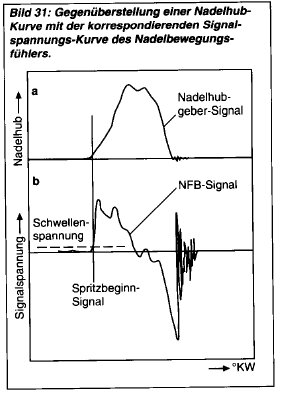
When I pulled this black connector (3-pin), the engine stopped. However, with a functioning NHG (Neutral Heat Gauge), it should then run in emergency mode, according to the 'VW 1.9l-TDI industrial engine' documentation.
no.
The vehicle's VP-EDC system immediately shuts off the engine when the crankshaft position sensor fails.
Emergency mode only in the industrial motor.
The PD-EDC system continues to function with certain brands of crankshaft position sensors, but those sensors also have a phase sensor on the camshaft. This provides more signals than the NBF sensor.
Sure, here is the translation of the text from German to English:
'Cu Gremlin'
Translated on 06-08-2026, 23:27.
|
|
| Back to top |
|
|
SeatArosa1.7SDI
Guest
Free account, no CAN development support
|
| 17-05-2004, 22:37 Subject: |
Quote |
|
The VP-EDC system in a vehicle immediately shuts off the engine when the crankshaft sensor fails.
That means my argument proving a defect in the NHG has failed?
With the 1.5V battery and a 47 Ohm resistor used as the load in parallel with the oscilloscope, I measured weak pulses. Perhaps the measurement setup wasn't ideal.
Now I will measure the voltage with an oscilloscope, while running the NHG system correctly (i.e., with the EDC connected), but in a way that isolates it from ground. To do this, I will use an isolation transformer.
If the NHG allows a direct current (DC) to flow through the EDC circuit, and if pulses are measured in parallel with it, this would likely provide evidence of the functionality of the circuit.
Best regards,
Translated on 06-08-2026, 23:29.
|
|
| Back to top |
|
|
SeatArosa1.7SDI
Guest
Free account, no CAN development support
|
| 17-05-2004, 22:41 Subject: |
Quote |
|
@Jan6k, thank you for the tip, I'll take a look at that.
Best regards,
Translated on 06-08-2026, 23:30.
|
|
| Back to top |
|
|
dieselmartin
Profi-Schrauber


Joined: 03/13/2003
Posts: 10121
Karma: +29 / -0 
Location: in der Werkstatt
2007 Volkswagen Passat
Premium Support
|
| 17-05-2004, 22:49 Subject: |
Quote |
|
AKU injector nozzle with NHG replacement for €181 at Volkswagen.
EUR 342 is the new price at Volkswagen.
2. Why does Ulf's statement about his three-pin plug contradict my picture? Nothing has yet been said about the cable that goes from the power source to his plug. 
(but I'm so sure that this is the person who parked it, just as I'm sure that I drive a TDI ).
Here's another wanted photo for the engine control unit:
(Please ignore the green circle; it is only relevant for turbochargers.)
http://people.freenet.de/golf-schrauber/Magnetventil.jpg
Here's the translation:
"Here is some additional information:"
8 - Stopper.
29 - Diesel temperature sensor (located in the ESP).
30 - Magnet valve for fuel injector control.
http://www.luxus-wg.de/~martin/auto_bilder/ESP.gifTransparency, Teamwork
... there was another T.
I don't know what the f*ck it was.
Translated on 06-08-2026, 23:31.
|
|
| Back to top |
Profile PM Garage |
|
Gremlin
Guest
Free account, no CAN development support
|
| 17-05-2004, 22:54 Subject: |
Quote |
|
Okay, so my ALH engine starts misfiring immediately, like a single-cylinder Eicher tractor, when I disconnect the NBF.
Sure, here is the translation of the text from German to English:
'Cu Gremlin'
| Description: |
|
| File size: |
23.31 KB |
| Viewed: |
11266 times |
|
Translated on 06-08-2026, 23:33.
|
|
| Back to top |
|
|
ulf
Profi-Schrauber
Joined: 04/13/2002
Posts: 11058
Karma: +18 / -0
Location: Saarland
2023 MG ZS
Premium Support
|
| 18-05-2004, 15:04 Subject: |
Quote |
|
Gremlin wrote: | | So, my ALH engine starts to misfire immediately, like a single-cylinder Eicher tractor, when I disconnect the NBF... |
@ArosaSDI:
You can obtain the same signal as shown in the "Gremlins" post by simply connecting both NBF wires to your oscilloscope while operating normally – that is, with the NBF connected to the EDC.
If nothing appears on the oscilloscope (despite correct operation and connection  ):
1. Measure whether the EDC is supplying a DC offset voltage (approximately 1 or 2 volts).
Second round of the NBF test.
3. If conditions 1 and 2 are met -> mechanical NBF (No Brake Function) defect. Gruß Ulf
_________
MG4 Electric
Translated on 06-08-2026, 23:34.
|
|
| Back to top |
Profile PM Garage |
|
SeatArosa1.7SDI
Guest
Free account, no CAN development support
|
| 18-05-2004, 21:32 Subject: |
Quote |
|
Hey guys!
1. Measure whether the EDC is supplying a DC offset voltage (approximately 1 or 2 volts).
Second round of the NBF test.
3. If conditions 1 and 2 are met -> mechanical NBF (No Brake Function) defect.
1.) 3.6V
2.) 115 Ohms
'With the 1.5V battery, I saw pulses that resembled those in the Gremlins diagram. However, they were very weak, and the sunlight was very bright. I have now finished my measurement adapter with an isolation transformer and will occasionally oscilloscope the original NHG voltage. Ideally, after 9:00 PM, so that something can be seen, and I can also take photos for you.'
2. Why does Ulf's statement about the 3-pin plug contradict my picture?? Nothing has been said yet about the cable that goes from the power source to his plug.
I understood Ulf's statement as follows: At the ESP, the connector for the pump has 3 contacts, which contain a shut-off and a flow control mechanism. Sorry for the misunderstanding. He probably meant the connector at the cable end on the EDC side.
Best regards,
Translated on 06-08-2026, 23:37.
|
|
| Back to top |
|
|
ulf
Profi-Schrauber
Joined: 04/13/2002
Posts: 11058
Karma: +18 / -0
Location: Saarland
2023 MG ZS
Premium Support
|
| 18-05-2004, 21:34 Subject: |
Quote |
|
SeatArosa1.7SDI wrote: | | He probably meant the connector at the cable end on the EDC side. |
Correct Gruß Ulf
_________
MG4 Electric
Translated on 06-08-2026, 23:39.
|
|
| Back to top |
Profile PM Garage |
|
SeatArosa1.7SDI
Guest
Free account, no CAN development support
|
| 18-05-2004, 21:43 Subject: |
Quote |
|
|
Translated on 06-08-2026, 23:40.
|
|
| Back to top |
|
|
SeatArosa1.7SDI
Guest
Free account, no CAN development support
|
| 20-05-2004, 18:32 Subject: |
Quote |
|
Hey everyone, there's some new information about the needle injection valve. I've now oscillographed it using a proper measurement adapter, and the NHG (needle injection valve) is producing good pulses.
http://www.luxus-wg.de/~martin/auto_bilder/SeatArosa/Oszillogramm%20NBF2.jpg Unfortunately, my old oscilloscope had difficulty triggering the time deflection properly, but I managed to take 2 good photos. I sent them to dieselmartin. If he uploads them to his website, you can see them. Also, I found the EDC in the cavity under the windshield wipers and took a picture of it as well. (see photo)
This also means that the fault can be narrowed down to the fuel injection control unit. Unfortunately, I didn't find a 3-pin connector on the EDC, but rather two multi-pin connectors. Perhaps I should have disconnected them, but it was very difficult to access them.
Regarding the injection pump, I initially thought that the injection timing adjuster cable was included in the large pump connector (see photo link). When I tried to unscrew the large rectangular pump connector, I noticed two things:
1.) Only in 3 out of the 4 holes were M4 brass Torx screws installed. The 4th screw was a steel Allen head bolt, which my socket wouldn't fit because the hex head is recessed in the hole. Workshop carelessness???
2.) When I slightly lifted the loosely screwed connector, fuel leaked out, so I immediately pressed it back down. Is it normal for there to be fuel in that part (see photo)? The connector contains approximately 8 wires. It includes the fuel injector and the flow regulator, is that correct? http://www.luxus-wg.de/~martin/auto_bilder/SeatArosa/ESP-Stecker%20+%20Schrauben.jpg
A two-wire cable leads to the injection start controller. Based on my current understanding, the injection start controller is a proportional valve that is controlled by pulsed voltage (pulse width modulation). Is this correct?
Okay, so I'm going to have to tap into the injection timing adjuster cable. Does anyone know common voltage, resistance, and current values?
Sure, here's the translation:
'Thank you in advance.'
Regards,
EDIT: In the 3rd paragraph, I wrote 'EDC' instead of 'ESP,' which obviously resulted in nonsensical content. I have corrected it and bolded 'fuel injection pump.' Damn abbreviations! 
Translated on 06-08-2026, 23:43.
|
|
| Back to top |
|
|
ulf
Profi-Schrauber
Joined: 04/13/2002
Posts: 11058
Karma: +18 / -0
Location: Saarland
2023 MG ZS
Premium Support
|
| 20-05-2004, 20:12 Subject: |
Quote |
|
SeatArosa1.7SDI wrote: | A two-wire cable leads to the injection start controller. According to my current information, the injection start controller is a proportional valve that is controlled by pulsed voltage. (Pulse width modulation). Is this correct?
Okay, so I'm going to have to tap into the injection timing adjuster cable. | Does anyone have common voltage, resistance, and current values?
Hi,
Have you already gone through} this?
Contrary to the title, this may also apply to the "exotic" SDI pump... Gruß Ulf
_________
MG4 Electric
Translated on 06-08-2026, 23:47.
|
|
| Back to top |
Profile PM Garage |
|
SeatArosa1.7SDI
Guest
Free account, no CAN development support
|
| 20-05-2004, 20:35 Subject: |
Quote |
|
Yes, Ulf, I've already gone through that. My initial 'is this correct?' was unnecessary . However, it doesn't contain the typical electrical values for this solenoid valve, especially the electrical resistance. For the unlikely event that the fuel injection timing advance coil has a short circuit or is faulty.
Unfortunately, I just found a case in the forum where the injection start adjustment piston was defective. That would really be a disaster .
To what extent can a mechanically defective (jammed) injection start regulator be repaired? What are the most common specific causes of failure? In my opinion, it should be possible to easily replace the solenoid valve itself, but certainly not the control piston.
Now, the electrical testing of the injection start adjuster is scheduled to take place.
Best regards,
Translated on 06-08-2026, 23:49.
|
|
| Back to top |
|
|
ulf
Profi-Schrauber
Joined: 04/13/2002
Posts: 11058
Karma: +18 / -0
Location: Saarland
2023 MG ZS
Premium Support
|
| 20-05-2004, 20:39 Subject: |
Quote |
|
SeatArosa1.7SDI wrote: | Yes, Ulf, I've already gone through that; my initial "is this correct?" was unnecessary . However, it doesn't contain the typical electrical values for this solenoid valve, especially the electrical resistance. For the unlikely event that the fuel injection timing advance coil has a short circuit or is loose.
|
Okay, I will add it.
According to the repair manual, the fuel injector resistor should have a resistance of 12-20 ohms. Gruß Ulf
_________
MG4 Electric
Translated on 06-08-2026, 23:50.
|
|
| Back to top |
Profile PM Garage |
|
dieselmartin
Profi-Schrauber
Joined: 03/13/2003
Posts: 10121
Karma: +29 / -0
Location: in der Werkstatt
2007 Volkswagen Passat
Premium Support
|
| 20-05-2004, 21:27 Subject: |
Quote |
|
New images are now available online.
http://www.luxus-wg.de/~martin/auto_bilder/SeatArosa/
Okay, please provide the German text you would like me to translate into English. I will only provide the translation. Transparency, Teamwork
... there was another T.
I don't know what the f*ck it was.
Translated on 06-08-2026, 23:51.
|
|
| Back to top |
Profile PM Garage |
|
SeatArosa1.7SDI
Guest
Free account, no CAN development support
|
| 20-05-2004, 21:47 Subject: |
Quote |
|
Okay, here's the oscilloscope image as promised. The Y-axis deflection factor is 3 V/cm, and the signal has been upscaled by a factor of 4.2. You can clearly see the centimeter grid.
http://www.luxus-wg.de/~martin/auto_bilder/SeatArosa/Oszillogramm%20NBF.jpg
Okay, so the amplitude of the NHG signal should be approximately pi * 2V ( (3cm * 3V) / 4.2 ).
Best regards,
Translated on 06-08-2026, 23:52.
|
|
| Back to top |
|
|
|


 Bookmarks
 Links
Links Garage
 FAQ, Legal Notice & Privacy
 RSS Feed
 Register
 Login
Login


