Should I perform a test run here first, or should I start searching directly on the VTG linkage?
Which types of medical devices should be logged, or is it sufficient to only log medical device type 11?
Am I correct in assuming that the values in the error log represent pressures?
Does it refer to a deviation once from the target value (1754.4 mbar) and once from the actual value (2142.0 mbar)?
Should I perform a test run here first, or should I start the search directly on the VTG linkage?
Good question . I will first check the adjustment range.
BM wrote:
Which type of material waste bin (MWB) is it reasonable to log, or is MWB 11 sufficient?
1 and 11 are enough.
BM wrote:
Am I correct in assuming that the values in the error log represent pressures?
Does it refer to a deviation once from the target value (1754.4 mbar) and once from the actual value (2142.0 mbar)?
Yes.
BM wrote:
And how can the error be best provoked?
I would suddenly floor the accelerator pedal (and keep it floored) while in 5th gear at 2500 rpm.
Here's a small consolation: The loader is working well. Please also check if the DPF is okay and not "too permeable." You can also check this beforehand by performing a diagnostic log and checking the differential pressure in the measurement blocks, starting from value 67.
Okay, I'll get started on it. I have until Saturday to complete it.
Quote:
Is the engine control unit original?
The vehicle is not modified, I think it's original. The customer is reliable.
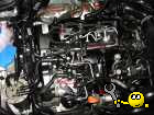
I'm currently considering (assuming the VTG is stuck), whether I should disassemble the turbocharger for cleaning.
Or whether it's worth trying to just unscrew the lower part of the frame and, using a Gloria sprayer or, even better, a cavity gun (which sprays around corners), along with a cleaning solution (that dissolves soot), attempt to clean it, and then follow up with a generous application of WD40. I don't have much experience with this, so I'm not sure if it would be effective.
3B5 AJM
Wer nichts weiss, muss alles glauben.
**Technische Fragen bitte ins Forum und nicht in mein Postfach**
I'm currently considering (if VTG is involved), whether I should disassemble the turbo for cleaning.
or whether it's worth trying to just unscrew the lower part of the frame
and using a Gloria sprayer or, better yet, a cavity gun (which also sprays around corners) and a cleaning solution (that dissolves soot) to start a cleaning process, and then follow up with a dose of WD40. I have little experience with this, and I'm not sure if it makes sense. } Often, it's not soot that's the main problem, but severe rust on the back plate!
Just let it go.
or whether it's worth trying to just unscrew the lower part of the frame and, using a Gloria sprayer or, even better, a cavity gun (which sprays around corners), and a cleaning solution (that dissolves soot), attempt to clean it, and then apply a dose of WD40 afterwards. I have little experience with this, and I'm not sure if it would be effective.
I estimate the chances of success to be rather low. You can try unscrewing the VTG canister on the loader and see if the VTG moves easily from stop to stop. It should move super easily (click-clack).
The weight of the can hanging from the lever arm alone results in a force that is several times greater than the normal operating force.
Tip: For the rear bolt connecting the exhaust manifold to the turbocharger, you'll need a slim 13mm ring wrench. I simply modified one with a rotary tool to fit mine.
Quote:
According to the documentation, just the installation or removal should take at least 3.6 hours.
If you're doing it for the first time, it's great. Compared to the transversely mounted engines, it's a dream .
Be careful with the exhaust temperature probe cable.
Here's another idea because the mileage seems right - take a look (and I'm serious this time, because I've seen it twice already!) at what the minimum flow screw looks like and the spot on the lever where it makes contact.
The screws or the lever wear down slightly, which causes the VTG (Variable Geometry Turbine) to close too much!
Half a turn and the error is gone.
Before you wrench off a size 13, it might have been a size 12 wrench... so, check the easily accessible nuts first . I'm not sure about that right now.
It's enough to simply unscrew the DPF from the turbocharger (3 screws).
Okay, finally found some time to tackle the thing with 20 interruptions.
Quote:
Before you tear apart a size 13, maybe it was actually a size 12 wrench...
They are all size 12. I have size 13 in some variations, but not in size 12. Because of this, the expansion process turned out to be a bit more difficult than initially anticipated.
First, let me clarify: Neither soot nor rust were the problem, but rather material defects at the bottom of the casting housing, where the guide vanes rest.
The turbocharger would really be better off in the trash.
After removing the protective cover, you can already see in Image 1 where the dog is buried, even before cleaning. The same is visible in Image 2.
After cleaning with a commercial cleaner (spray, let it sit, rinse).
You can see it again very clearly in images 3 and 4. The advantage of this method is that it doesn't obscure any traces.
After further cleaning and reattaching the variable geometry turbocharger (VGT) adjustment mechanism, I discovered that it was still sticking.
Specifically, a guide vane (facing open towards the direction of rotation) was jammed at the location shown in images 1 and 2.
It only opened 50%, and then it got stuck, just like before.
Interestingly, even when in the closed position (with the adjustment mechanism engaged), it had the same amount of axial play as the others. However, when opened, it lost that space.
Okay, I re-monitored the Vtg system and searched for errors. I couldn't find anything on the guide vane itself that would explain the jamming.
After that, I took a piece of a body filler file and scraped it around the bottom of the housing. If everything is level, it should slide almost effortlessly over the material. If not, you can remove material from where it's too high, and you'll see what's going on.
In image 5, you can see a bright spot at the edge near the swirl channel, which indicates where the file was used. (The Edding marking was added later.)
To verify my assumption, I then checked the clearance (of the swirl channel) with a drill bit. As expected, the drill bit could not be inserted into the swirl channel without scraping against the bottom.
Afterwards, I painstakingly worked by hand to restore the area until the guide vane had the same amount of clearance in every position as all the others. I used a permanent marker as a tool. I could have also modified the guide vane itself, but I didn't want to. Instead, I simply smoothed it.
In image 6 and the video clip, you can see the working VTG. This shows how easily the VTG can be moved.
To cut a long story short -- I have to install this thing again now. Fun factor = 0.
PS: The connecting screw and lever were found to be in good condition.
Boost Pressure Control: Limit Exceeded - Clip.avi
Description:
Boost Pressure Control: Limit Exceeded
File size:
1.55 MB
Viewed:
4270 times
Img_6.jpg
Description:
Boost Pressure Control: Limit Exceeded
File size:
1.92 MB
Viewed:
6513 times
IMG_5.jpg
Description:
Boost Pressure Control: Limit Exceeded
File size:
903.62 KB
Viewed:
5857 times
IMG_4.jpg
Description:
Boost Pressure Control: Limit Exceeded
File size:
888.47 KB
Viewed:
5523 times
IMG_3.jpg
Description:
Boost Pressure Control: Limit Exceeded
File size:
1023.07 KB
Viewed:
5651 times
IMG_2.jpg
Description:
Boost Pressure Control: Limit Exceeded
File size:
963.69 KB
Viewed:
5482 times
IMG_1.jpg
Description:
Boost Pressure Control: Limit Exceeded
File size:
986.39 KB
Viewed:
5527 times
3B5 AJM
Wer nichts weiss, muss alles glauben.
**Technische Fragen bitte ins Forum und nicht in mein Postfach**


 Bookmarks
 Links
Links Garage
 FAQ, Legal Notice & Privacy
 RSS Feed
 Register
 Login
Login






 . I will first check the adjustment range.
 You can also check this beforehand by performing a diagnostic log and checking the differential pressure in the measurement blocks, starting from value 67.