| Author |
Message |
Phaidros
Schrauber

Joined: 09/23/2016
Posts: 56
Karma: +13 / -0 
Premium Support
|
 15-02-2018, 17:12 Subject: Fragen zu Luft-Zuheizer (Z35) mit PTC-Element + Steuergerät 15-02-2018, 17:12 Subject: Fragen zu Luft-Zuheizer (Z35) mit PTC-Element + Steuergerät |
Translating... |
|
[Translating...] Defekte elektrische Luft-Zuheizer (erwärmt die Einströmluft im Klimakasten, kein eigenes Heizgerät) mit nicht löschbarem Fehler wurden hier ja schon öfters diskutiert, siehe z.B. https://community.dieselschrauber.org/en/viewtopic.php?t=26006 und vor allem https://community.dieselschrauber.org/en/viewtopic.php?t=28328.
Ich meine die Luftzusatzheizung (Z35) mit PTC-Element, siehe Fehlermeldung unten - nicht eine explizite Zusatzheizung. Ich habe die Version mit Steuergerät (J604), welche im Passat 2006 B6 bis KW 43/06 verbaut wurde.
Die übliche Lösung ist hier (aus dem zweiten der eben genannten Links):
Quote: | | Geholfen hat ein Nachlöten der 5 größeren Widerstände auf der Platine, diese hatten wahrscheinlich kalte Lötstellen. Die Heizung funktioniert seitdem wieder. |
Ich habe jedoch auch gelesen, dass häufig auch das Steuergerät defekt ist.
Verblüffend finde ich bei der oben beschriebenen Lösung natürlich, dass das Ding bei der Stellglieddiagnose heizt, aber sonst nicht (Nicht angesteuert wird? Das würde ja bei Minus-Temperaturen eher für ein Steuergerät-Defekt sprechen.)
Daher zwei Fragen, bevor ich das Ding ausbaue (was ja ziemlich fummelig sein soll):
- Wenn das Steuergerät antwortet, Werte ausgibt und eine Stellglieddiagnose durchführt (siehe Bild unten), kann es ja selbst kaum defekt sein, oder?
- Wieso heizt der Zuheizer in der Stellglieddiagnose, sonst aber nie? (Temperaturen unter Null. Fehlermeldung ist ja auch vorhanden.)
Mehr eine theoretische Frage, aber es leuchtet mir nicht so wirklich ein, dass es per Diagnose gehen soll, nicht aber bei normaler Ansteuerung
(sofern diese erfolgt, aber falls nicht, wäre es ja wieder ein Steuergeräte-Problem, nicht eines der nachzulötenden Widerstände?)
Sind die im Bild gezeigten Werte eigentlich realistisch? (Ich hatte auch von höherer Leistung und größeren Strömen gelesen, die Stellglieddiagnose hatte aber nur eine einzige Option mit dem gezeigten Ergebnis.)
Quote: | Adresse 7D: Zuheizer Labeldatei: DRV\1K0-963-235.lbl
Teilenummer SW: 1K0 963 235 E HW: 1K0 963 235 E
Bauteil: PTC-Element 0404
Revision: 00800000 Seriennummer:
Betriebsnr.: WSC 00000 000 00000
VCID: 2D56C4E2B48F672E11-8078
1 Fehler gefunden:
00361 - Heizelement für Zusatzheizung (Z35)
014 - defekt
|
Quote: | Erweiterte Identifikation
Seriennummer:
Identifikation: BEB-001
Revision: 00800000
Datum: 06.06.06
Prüfstandsnummer: 2100
Herstellernummer: 4072
Software: K0404
Sonstiges: Hardwarenummer: 1K0 963 235 E
VCDS Info:
VCID: 2D56C4E2B48F672E11-8078
Labeldatei: DRV\1K0-963-235.LBL |
Fehlerhinweise (engl.) bei Ross Tech zu Fehler 00361: http://wiki.ross-tech.com/wiki/index.php/00361
| Description: |
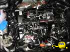
| Fragen zu Luft-Zuheizer (Z35) mit PTC-Element + Steuergerät |
|
| File size: |
45.49 KB |
| Viewed: |
3774 times |
 mit PTC-Element + Steuergerät")
|
Last edited on 15-02-2018, 17:57, edited 7 times in total.
|
|
| Back to top |
Profile PM |
 |
guste100
Profi-Schrauber


Joined: 07/27/2004
Posts: 2400
Karma: +436 / -0
Location: Mitte Schleswig Holsteins
2007 Volkswagen Passat
Premium Support
dieselschrauber likes this. |
| 15-02-2018, 17:40 Subject: Fragen zu Luft-Zuheizer (Z35) mit PTC-Element + Steuergerät |
Quote |
|
Speculation:
In actuator diagnostics, the transistor is simply switched on and off.
Under normal operation, for example, the voltage supply, power consumption, or parameter 42 are monitored. If only the latter component is defective, then the actuator diagnostics and normal operation will not function.
Comparable to cheap LED light bulbs (with insufficient power consumption) in a car: they light up for 3 seconds and then turn off, and are then registered as defective in the error memory. It works, but the parameters for normal operation are not correct.
Greetings.
Guste.
Translated on 03-07-2026, 15:19.
|
|
| Back to top |
Profile PM Garage |
|
Phaidros
Schrauber
Joined: 09/23/2016
Posts: 56
Karma: +13 / -0
Premium Support
|
| 15-02-2018, 17:48 Subject: Fragen zu Luft-Zuheizer (Z35) mit PTC-Element + Steuergerät |
Quote |
|
Quote: | | Why does the auxiliary heater activate during actuator diagnostics, but never at any other time? |
A theory I recently read (in an English forum) suggests that the total heating power is likely 1000 watts (with a current of 70 amps).
Quote: | A heating power of 600 watts indicates that only 2 (out of a total of three) heating elements are functioning.
Probably, this is why the entire heating unit is identified as defective by the control unit and not used. |
Maybe it's just a theory, but it sounds pretty convincing to me (as an answer to my original question).
And please answer my further question about whether the power shown in the actuator diagnosis image is likely correct (it's currently at 2/3 of the rated power).
So, it's probably the recommended approach to resolder those five resistors on the circuit board.
While I've done some soldering and crafting before, I haven't yet worked with SMD components (i.e., soldering components directly onto the circuit board from above). I'll need to do some research on that first...
And I'm not really looking forward to the expansion either.
Translated on 03-07-2026, 15:19.
|
|
| Back to top |
Profile PM |
|
Phaidros
Schrauber
Joined: 09/23/2016
Posts: 56
Karma: +13 / -0
Premium Support
|
| 15-02-2018, 17:55 Subject: Fragen zu Luft-Zuheizer (Z35) mit PTC-Element + Steuergerät |
Quote |
|
Quote: | | During normal operation, for example, the voltage supply, the power consumption, or parameter 42 are monitored. If only the latter is defective, then the actuator diagnosis and normal operation will not work. |
Yes, something like that, that makes sense.
See my reply to myself  from earlier, which overlapped with yours. Same thought.
Best regards!
Translated on 03-07-2026, 15:19.
|
|
| Back to top |
Profile PM |
|
abicim
Joined: 11/27/2020
Posts: 23
Karma: +7 / -0
Location: Furtwangen
Premium Support
|
| 04-12-2020, 22:21 Subject: Fragen zu Luft-Zuheizer (Z35) mit PTC-Element + Steuergerät |
Quote |
|
I'm having the exact same problem.
- Heating element for auxiliary heater (Z35)
014 - defective
- Diagnostic interface for data bus (J533): not present or incorrect.
005 - Basic settings / Adaptation.
I bought a used "tested" item from a seller on eBay, and I installed it today, but it has the exact same problem.
After installation, I activated the auxiliary heater using the actuator diagnostics, and it only reached approximately 600 watts and then slowly decreased to around 300 watts.
Has anyone had any success with soldering or using an oven?
| Description: |
|
| File size: |
276.59 KB |
| Viewed: |
730 times |

|
| Description: |
|
| File size: |
331.51 KB |
| Viewed: |
677 times |

|
Translated on 03-07-2026, 15:19.
|
|
| Back to top |
Profile PM |
|
guste100
Profi-Schrauber
Joined: 07/27/2004
Posts: 2400
Karma: +436 / -0
Location: Mitte Schleswig Holsteins
2007 Volkswagen Passat
Premium Support
dieselschrauber likes this. |
| 07-12-2020, 10:31 Subject: Fragen zu Luft-Zuheizer (Z35) mit PTC-Element + Steuergerät |
Quote |
|
I don't have any practical experience working on that specific control unit yet. But generally:
Surface mount soldering isn't rocket science. A reasonably fine soldering tip with a moderately powerful soldering iron should be sufficient for the job. Here, it's even about power resistors, so the power rating is more important than the fine tip.
If you have a DSLR or another camera with a decent macro function, you should be able to see the cracked solder joints. If you upload the image here, we'd be happy to help. You should still have that old control unit lying around somewhere.
The air heater consists of three heating elements. Similar to the Golf 3 era, with its three glow plugs in the water circuit. Depending on the voltage and temperature, either the low setting (one heating element) or the high setting (two heating elements) is activated, or both settings (all three heating elements) can be used. Based on the problems I'm reading here, it seems like the issue always arises with the smaller setting (the individual heating element).
That explains why the control unit sets the error, but still gets warm during diagnosis (thanks to the large heat sink).
So, it just needs to solder that small component in place.
PS 2: In the Passat 3C, the PTC heater was only used in the first few model years (I believe 2006 and 2007). Afterwards, the three heating elements were directly controlled by external relays (I believe from 2008) onwards). It seems they realized that a power control unit was not necessary for a simple heating element. It was probably originally intended to be a fast-responding PWM controller, but it was never actually implemented that way.
Regards,
Guste.
Translated on 03-07-2026, 15:19.
|
|
| Back to top |
Profile PM Garage |
|
abicim
Joined: 11/27/2020
Posts: 23
Karma: +7 / -0
Location: Furtwangen
Premium Support
|
| 07-12-2020, 10:45 Subject: Fragen zu Luft-Zuheizer (Z35) mit PTC-Element + Steuergerät |
Quote |
|
Thank you, Guste, for the detailed explanation and assistance.
This weekend, I removed the auxiliary heater from my brother's car (he has the same model) and resoldered the five resistors.
Before the upgrade, it had a maximum output of 300 watts during the actuator diagnosis.
First, I put the circuit board in the oven at 180 degrees Celsius for about 10 minutes.
After the oven, it went up to a maximum of 700 watts, but it still displayed the same error message.
Subsequently, it was expanded again, and the five resistors were "resoldered" by keeping the soldering iron on the resistor for approximately 5-8 seconds, with the tip also touching the connection point. However, it still has errors and is only capable of up to 700 watts.
"How do I know which is the small step and which is the large step on the circuit board?"
Translated on 03-07-2026, 15:19.
|
|
| Back to top |
Profile PM |
|
guste100
Profi-Schrauber
Joined: 07/27/2004
Posts: 2400
Karma: +436 / -0
Location: Mitte Schleswig Holsteins
2007 Volkswagen Passat
Premium Support
dieselschrauber likes this. |
| 07-12-2020, 14:06 Subject: Fragen zu Luft-Zuheizer (Z35) mit PTC-Element + Steuergerät |
Quote |
|
abicim wrote: | | First, I put the circuit board into the oven at 180 degrees for about 10 minutes. |
Uh, that's quite a crude method. I'm not sure if that was a good thing.
Most electronic components are not designed to withstand this temperature. Typically, they are specified for use up to 125°C in the automotive industry. Of course, this temperature for soldering can be exceeded, but 10 minutes is significantly longer than the soldering profiles I am familiar with.
Furthermore, soldering is typically performed with a peak temperature of approximately 240°C. In short: The duration might have been too long for some components, and the temperature might have been too short for the solder.
In mass production, a proper soldering oven follows very specific soldering profiles. For example, the temperature is precisely controlled by a ramp that increases to nearly 200°C within 2-3 minutes, then rapidly increases to 240°C within less than 60 seconds, and then decreases again.
abicim wrote: | (..) However, it still has flaws and only works up to 700 watts.
How do I know which one is the small step and which one is the large step on the circuit board? |
To do this, you need to examine the layout of the conductive traces. Please post a high-resolution and clear photo, and then we'll have a chance to help.
As mentioned, it's possible that you may have already killed something in the oven.
Translated on 03-07-2026, 15:19.
|
|
| Back to top |
Profile PM Garage |
|
dieselschrauber
Administrator

Joined: 04/12/2002
Posts: 18044
Karma: +791 / -0
Location: St.Gallen
2018 Volkswagen T6 
|
| 08-12-2020, 21:17 Subject: Fragen zu Luft-Zuheizer (Z35) mit PTC-Element + Steuergerät |
Quote |
|
Hi,
Quote: | | Furthermore, soldering is typically performed with a peak temperature of approximately 240°C. In short: The time may have been too long for some components, and the temperature may have been too short for the solder. |
Okay, here's the translation:
"That's correct. The thing with the oven probably caused more harm than good; electrolytic capacitors, in particular, don't like prolonged exposure to high temperatures." At 180°C, with typical lead-free soldering fluxes, very little bonding is likely to occur.
I recommend soldering the connections manually using a soldering iron.
Best regards, Rainer.
| Description: |
| Übliches Lötprofil für bleifreies Lötzinn. |
|
| File size: |
404.25 KB |
| Viewed: |
699 times |

|
Translated on 03-07-2026, 15:19.
|
|
| Back to top |
Profile PM WWW Garage |
|
abicim
Joined: 11/27/2020
Posts: 23
Karma: +7 / -0
Location: Furtwangen
Premium Support
Flac likes this. |
| 19-12-2020, 21:32 Subject: Problem solved |
Quote |
|
Hello everyone,
I'd like to provide a quick update. Since I didn't have the professional equipment needed to potentially solve the problem, and after many unsuccessful attempts, I sent the auxiliary heater to ecu.de for repair. They repaired the circuit board, tested it, and sent it back. The whole thing cost 145 euros, mostly due to the extra effort (resulting from the unsuccessful attempts).
After that, I installed the auxiliary heater today and first read the error memory, and lo and behold, there were no more error messages stored.
Then the engine was started, and the actuator diagnostics were run. As can be seen from the Screenshot, the 1,000 watts are almost reached. I immediately felt the warm air flowing out.
Thank you to everyone for your support.
Best regards, Orhan.
| Description: |
|
| File size: |
19.95 KB |
| Viewed: |
569 times |

|
| Description: |
|
| File size: |
29.8 KB |
| Viewed: |
486 times |

|
Translated on 03-07-2026, 15:19.
|
|
| Back to top |
Profile PM |
|
dieselschrauber
Administrator
Joined: 04/12/2002
Posts: 18044
Karma: +791 / -0
Location: St.Gallen
2018 Volkswagen T6
|
| 20-12-2020, 10:01 Subject: Fragen zu Luft-Zuheizer (Z35) mit PTC-Element + Steuergerät |
Quote |
|
Thank you for the feedback! 
Translated on 03-07-2026, 15:19.
|
|
| Back to top |
Profile PM WWW Garage |
|
|

