
| Diesel, Engine Technology and Vehicle Technology. Repair, Maintenance and Diagnostics (OBD). |
VCDS: Troubleshooting Performance Issues (Articles) |
|
|
| 🔗 ⭐ 🖨 |
| VCDS: Troubleshooting Performance Issues | |
|---|---|
ulf  14-07-2003, 18:49 14-07-2003, 18:49 |
|
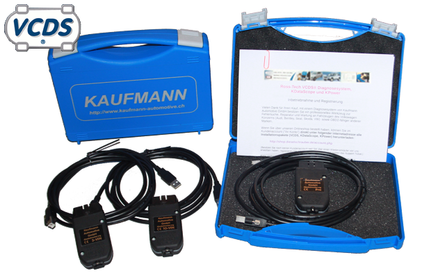 This should serve as a guide on how to identify fuel system losses in VP (TDI with distributor pump), PD engines (pump-injector injection), and the newer CR engines (common rail injection) using VAGCOM / VCDS, without excessive detours and dead ends. And here's the big disappointment for those who expect a quick-fix solution from digital diagnostics: If there is only a loss of power, the error memory is often empty! In order to find the causes, it is necessary to identify and read out the relevant measurements while the problem is occurring. Basic tests Since simple causes for performance issues are difficult to identify definitively with VCDS, the standard diagnostic procedures should be performed first. VP and PD motors: Is the fuel filter drained, replaced within the recommended intervals, and not, for example, clogged by a wave of biodiesel sludge? Is the fuel filter in the tank clogged? Fuel lines should be airtight and free of leaks, and there should be no large air bubbles in the clear intake hose between the fuel filter and the injection pump (unfortunately, this is not always easy to check with PD-TDIs due to the lack of a clear hose). CR engines: Insufficient fuel supply manifests as difficulties in regulating fuel pressure/rail pressure. If the rail pressure is significantly lower than the target pressure at high load and engine speed, there is a problem with the fuel supply, the high-pressure pump, or the pressure regulation system. All engines: Are the air filter and intake passages clear? No dragging brakes? When coasting to a stop, the vehicle should come to a standstill smoothly, without any noticeable jolts. After driving at least 10 km without heavy braking, no rim should be noticeably warm (or warmer than the others). Basic information about measurement blocks and advanced measurements: Measurement blocks (MBs) can be found in older engine control units. Newer engine control units have extended measurement values, which have different numbers and names. However, you can search for the necessary measurement values in the extended measurement values section of VCDS using a text search. Collections of extended measurement values can be saved/loaded in VCDS, which eliminates the time-consuming process of searching through the extensive (sometimes hundreds) of measurement values provided by the engine control unit. Collections of extended measurement data, categorized by engine code, are planned for this section. Extended measurements Read error codes with VCDS If the loss of power is caused by a limp-home mode, there is usually an entry in the error memory. Therefore, the error memory should be read out as soon as possible, preferably with a complete vehicle scan. This is because: if an error no longer occurs after a certain number of engine starts, it is automatically deleted from the memory. If VCDS is already running, you should perform a few more checks to identify or rule out simple causes of the problem. -> In MWB 7, the temperatures should be within +/- 3°C of each other when the engine is cooled down, and should be plausible when the engine is running. -> In MWB 10, the charging pressure and external pressure should be approximately equal (within about 20 mbar) when the engine is stationary. -> In MWB 2 or 10, the pedal position should display a stable reading of 100% when the accelerator pedal is fully depressed (the engine can be off, but the ignition should be on). -> In MWB 6, both brake switch bits should change state simultaneously, indicating that the clutch is being engaged. For CR engines, the corresponding measured values may sometimes be found in the extended measurement data blocks. Recording of measurement data via VCDS data logging Assuming everything is generally okay, and when driving at full throttle in 3rd or 4th gear, you should log and analyze the following diagnostic data blocks (DTCs) within a speed range of at least 2500 to 4000 rpm. "Regarding the initial fuel injection quantity limits (MWB 8 and 9): The torque limit should specify the lowest value. If the air mass/soot limit is significantly lower, it indicates a potential issue with the turbocharger system (including the vacuum system in VTG turbochargers) or the air mass sensor (MAF sensor)." Exception: In engines that have been chip-tuned, the soot reduction system may always be active at full load to avoid "wasting air." If the (software-optimally adjusted) engine is always "running rich" at full throttle, you should check the boost pressure (MWB 11). If the actual boost pressure, which is being controlled, consistently deviates from the target value by more than 0.1 bar, the turbocharging system should be checked and/or repaired. Exception: Tuning software with poorly implemented boost pressure control data can cause significant and persistent control errors, even without hardware defects. Whether the problem lies in the hardware or software can only be reliably determined by comparing it to the original software. If the boost pressure is largely correct, the cause of active cylinder deactivation often lies in the mass airflow sensor (MAF): verschandeln it (with brake cleaner or similar) or try replacing it with a known good one. Also, check the intake path between the MAF sensor and the turbocharger, as well as the crankcase ventilation system, for leaks and loose hoses, etc.! -> If the boost pressure is too low, also consider leaks in the pressure system (which can be identified by external oil traces and possibly by hissing or whistling sounds when accelerating). -> Insufficient boost pressure can also be caused by significant issues with the mass airflow sensor (MAF), even if the entire turbocharging system is perfectly functional! Check the boost pressure and mass airflow sensor (MAF) values. For V-twin engines, check the fuel injection timing (group 4). The deviation between the target injection start time and the actual injection start time should not exceed 2 degrees, except immediately after sudden load changes. Only VP engines: If the actual values fluctuate even during constant operation at partial load, the suspicion initially falls on the needle movement sensor (NBF, also known as a needle travel sensor), which often also causes jerking problems. A tap with a screwdriver handle on the injector at approximately 3000 rpm can reveal any potential malfunctions: the engine should not exhibit any misfires. If it does, replace the injector with a new one. If all injectors have exceeded approximately 100,000 km, it is advisable to consider replacing all of them. If the NBF (Nozzle Flow Balance) is intact, the injector adjustment mechanism in the pump, along with its electrical connections, must be checked. If the target value is only not reached at full load, and the duty cycle of the injection control valve is simultaneously above 95%, the pump setting should be temporarily adjusted to a later timing, so that a full-load duty cycle of around 90% is achieved. Further examinations Given the still inexplicably low air mass, the following points should be considered: 1. Overly hot intake air, possibly due to a heavily soiled air filter: The intake air temperature (IAT) can be read from the diagnostic module (OBD), field 3. For vehicles with an air filter located in the wheel well, the normal IAT at full throttle and 4000 rpm is typically 30 to 60 Kelvin above ambient temperature. For vehicles with an air filter located at the front, the maximum IAT is approximately 20 Kelvin above ambient temperature. In some engines, the turbocharger boost pressure is also reduced when the low-temperature threshold (LLT) exceeds certain limits; this is described in document MWB 7 in conjunction with document 11. Occasionally, specialists, for example during accident repairs, replace the spoiler grilles of the engine's air intake with solid panels, which can cause the engine temperature to rise to levels that were not intended. 2. A rare and difficult-to-detect cause of power loss is a constricted exhaust pipe, for example, due to fragments of a broken catalytic converter monolith that have become lodged and are causing an obstruction. Due to the excessive back pressure in the exhaust system, building up boost pressure is more difficult and may occur at higher engine speeds than usual. Furthermore, the restricted gas mass flow will also result in a low mass airflow (MAF) sensor reading, which naturally directs suspicion towards the MAF sensor. If cleaning or replacement of the MAF sensor, under normal boost pressure and with a functioning fuel injection system, yields no improvement, the exhaust system should be inspected for any pinched areas, and the catalytic converter housing should be checked for dents, etc. Sometimes, fragments of a broken catalytic converter can be detected by the rattling noise produced when tapping firmly on the exhaust system. With a severely constricted exhaust pipe diameter, even the normal pulsations of the exhaust flow may be partially or completely absent, pulsations that one can usually feel with their hand just behind the exhaust pipe when the engine is idling. 3. If the previous tests do not provide any clues about the cause of the performance loss, it is recommended to first perform a careful 2000 - 4000 rpm acceleration test} (requires Excel or Staroffice) in order to determine the magnitude of the problem. If all checks do not indicate any error messages, then the following should also be considered: -> a stuck-open AGR valve (often accompanied by a louder-than-normal full-throttle sound). -> Vacuum in the tank, which builds up slowly during driving due to a defective/stuck vent valve. This can, for example, allow air to be drawn into the supply line at hose clamp connections, which in VP 37 engines reduces the internal pressure of the pump and prevents the early timing of the injection start – leading to a loss of power. In the MWB 4, a duty cycle close to zero may be observed, which can also fluctuate depending on the air pocket at the outlet of the pump's return line – without necessarily indicating a defect in the pump. When a large amount of air is drawn in, it can sometimes enter the high-pressure section, leading to further power loss or hesitation. Test: With a low fuel level, perform a test drive without the fuel cap. If the normal power is available, then the "vacuum in the tank" problem is likely identified. "Significant oil vapor and soot deposits (approximately 5mm thick or more) are present in the intake manifold near the EGR valve and behind it, which obstruct the supply of fresh air; simultaneously, fuel consumption may also be increased." -> Incorrectly adjusted quantity valve in VP engines (often associated with starting problems). -> Engine wear (perform a compression test!). -> Significant wear on nozzles or pump, or high-pressure pump. -> Defective pressure control valve in the common rail of a CR engine. -> Incorrect fuel pressure of the tandem pump in PD engines and/or defective O-rings in the PD elements. -> adjusted engine control (e.g., twisted timing belt pulley, etc.), see also <ahref>Valve timing and PD units on the PD-TDI. -> Defects in the power supply lines of the EDC (Electronic Stability Control) or within the MSG (Modular Sedan Gearbox) itself (which may also be stored in the error memory). -> Fuel with a poor energy content and/or contaminants. What information about vehicles and control units is required? Given the large number of different model configurations, it is most helpful to include a complete VCDS Autoscan with any inquiries. The Autoscan clearly shows, through the respective VAG part numbers, software versions, and codings of the existing control units, what is installed in the vehicle and how it is configured. A complete VAG part number may or may not include one or two letters at the end of the number. For example, "03G 906 016 ME". If the VAG part number is incomplete, it has no meaning. Similarly, all recorded errors are clearly displayed in context, which is necessary when dealing with various problems to distinguish between causal errors and (harmless) consequential errors. Translated on 03-09-2026, 18:35. |
|
 |
|
| Ratings - VCDS: Troubleshooting Performance Issues | |
Average rating: 4.78 - worst rating: 2 - best rating: 5 - number of ratings: 23 - View ratings |
|
|
| 🔗 ⭐ 🖨 |
|
Foren- und Portal-Software: V7.8 © 2003 - 2026 Kaufmann Automotive GmbH, Embedded Software Freelancer & Shop für Kfz-Diagnosegeräte. Parse time: 0.040s
 |


 Bookmarks
 Links
Links Garage
 FAQ, Legal Notice & Privacy
 RSS Feed
 Register
 Login
Login

